Liquid-cooled battery module

Inactive Publication Date: 2014-09-18
GM GLOBAL TECH OPERATIONS LLC
View PDF1 Cites 26 Cited by
  • Summary
  • Abstract
  • Description
  • Claims
  • Application Information

AI Technical Summary

Benefits of technology

[0009]Accordingly, the present invention provides battery module cooling systems which reduce temperature variation in battery cells and maximum battery cel

Problems solved by technology

Uneven temperature distribution in the battery pack can lead to electrically unbalanced modules, and consequently to lower performance and shorter battery life.
Major thermal concerns of a battery pack are overheating and uneven heating within each individual battery cell and across the entire battery pack during operational charge/discharge cycles, which can lead to fast battery degradation and capacity reduction of battery cells.
Maintaining a uniform temperature within the battery cell is difficult because of non-uniform heat generation within the battery cell.
In addition, the heating and cooling systems can produce non-uniform heat transfer because of their internal thermal resistance.
The generation of propulsive power from the RESS also produces significant thermal loads.
These momentary peak load periods generate powerful electrical currents, causing significant warming of the Li-ion cells due to internal resistance.
At around 95 percent, charging and discharging efficiency is very high; however, the resulting waste heat cannot be ignored.
Coupled with the fact that, in the warmer weather and in warmer climates in particular, the temperature of the vehicle interior can rise to well in excess of 40° C., operating Li-ion bat

Method used


Image

  • Liquid-cooled battery module
  • Liquid-cooled battery module
  • Liquid-cooled battery module

Examples


Embodiment Construction

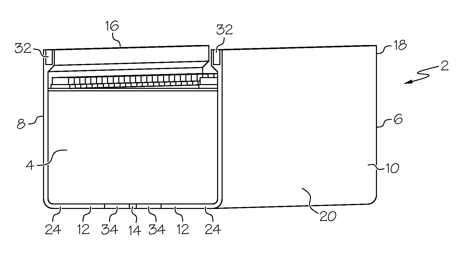
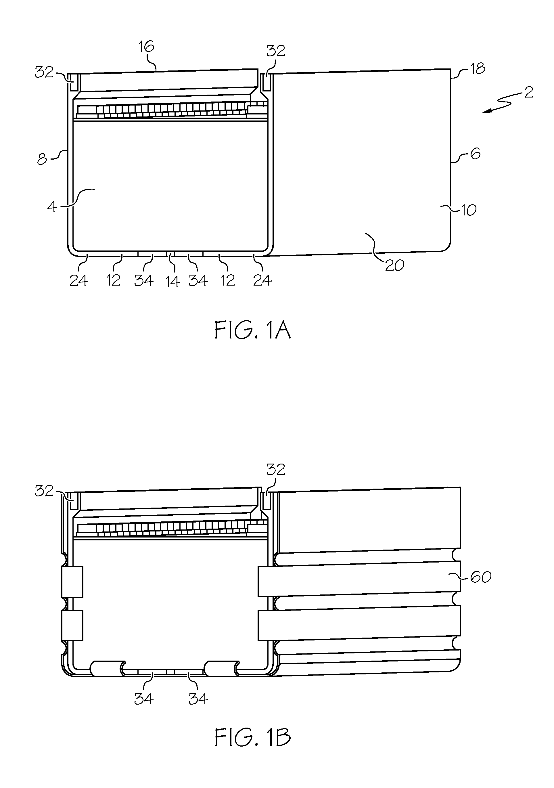
[0019]The present invention will now be described more fully hereinafter with reference to the accompanying drawings, in which exemplary embodiments of the invention are shown. The present invention may, however, be embodied in many different forms and should not be construed as being limited to the embodiments set forth herein. In other words, the present invention may be changed or modified using equivalents or substitutes without departing from the scope and spirit of the invention. In the following description, it is to be noted that, when the functions of conventional elements and the detailed description of elements related with the present invention may make the gist of the present invention unclear, a detailed description of those elements will be omitted.

[0020]It will be understood that although the terms “first,”“second,” etc. may be used herein to describe various elements, these elements should not be limited by these terms. These terms are only used to distinguish one e...


PUM

PropertyMeasurementUnit
Temperatureaaaaaaaaaa
Pressureaaaaaaaaaa
Pressure dropaaaaaaaaaa

Abstract

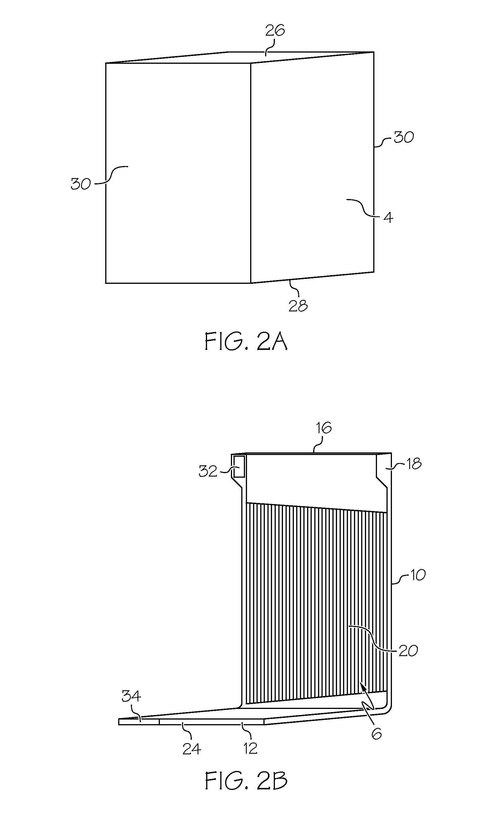
A battery module having a cooling plate assembly made from two non-contiguous cooling plates is provided. Each cooling plate has a side panel contiguous with a base panel, and the cooling plates are disposed opposite one another such that the base panels are coplanar and separated by a gap. An inlet duct runs along an upper edge of each side panel, and a manifold having coolant channels in fluid communication with the inlet duct is located in each side panel. The base panels have an outlet duct in fluid communication with the manifold. The cooling plate is designed to decrease friction loss as coolant flows through the inlet duct, manifold and outlet cut, and coolant channels in the manifold are designed to maintain a uniform flow rate across the manifold. Individual cells are disposed in the assembly such that the cell sides and bottoms are in heat-transfer contact with the plate side and base panels, respectively. The design of the battery module reduces operational temperature variation in the cells across the battery module and within each battery cell. Methods for reducing coolant flow friction loss, for establishing a more uniform coolant flow rate, and for reducing temperature variation are also provided.

Description

TECHNICAL FIELD[0001]The present disclosure relates to modules for lithium-ion and related batteries, and more specifically to cooling plate systems for battery modules which reduce temperature variation across the module and within individual battery cells.BACKGROUND[0002]Lithium-ion and related batteries, collectively known as a rechargeable energy storage system (RESS), continue to be considered a clean, efficient, and environmentally responsible power source for electric vehicles and various other applications. In particular RESS technologies are being used in automotive applications as a way to supplement, in the case of hybrid electric vehicles (HEVs), or supplant, in the case of purely electric vehicles (EVs), conventional internal combustion engines (ICEs). The ability to passively store energy from stationary and portable sources, as well as from recaptured kinetic energy provided by the vehicle and its components, makes batteries ideal to serve as part of a propulsion syst...

Claims


Application Information

Patent Timeline
IPC IPC(8): H01M10/6556H01M50/204H01M50/224
CPCH01M10/5057H01M2/1077H01M10/5004H01M10/5075H01M10/5016H01M10/5032H01M10/5008H01M50/224H01M50/204H01M10/625H01M10/647H01M10/6556H01M10/617H01M10/613Y10T29/49108H01M10/6567Y02E60/10
Inventor SUN, HONGGUANGDIXON, REGAN P.
Owner GM GLOBAL TECH OPERATIONS LLC
Why Eureka
Try Eureka