
Vacuum induction melting and strip casting equipment for rare earth permanent magnetic alloy

a technology of strip casting and vacuum induction melting, which is applied in the direction of magnetic bodies, foundry moulding apparatus, manufacturing tools, etc., can solve the problems of affecting the performance of products and still having a lot of products, and achieves improved production efficiency, high production performance, and good consistence

Active Publication Date: 2014-12-04
SHENYANG NORTH VACUUM TECH CO LTD
View PDF4 Cites 4 Cited by
  • Summary
  • Abstract
  • Description
  • Claims
  • Application Information

AI Technical Summary

Benefits of technology

The present invention provides a rare earth permanent magnetic alloy vacuum induction melting and strip casting equipment that completes the rare earth alloy vacuum and strip casting slice, thermal process and cooling in a protective atmosphere of one device. This improves production efficiency, performance, and consistence compared to existing vacuum induction heating and strip casting furnaces. The present invention avoids uneven slice stirring, slow cooling, low efficiency, and high power consumption. It also avoids slice adhesion and oxidizing the slice during logistics process. This results in improved production capacity, consistency of the product, increased service life, and decreased maintenance time of the equipment.

Problems solved by technology

By exploring, it is found that in spite that compared to the prior ingoting process and equipment, the product performance of the currently used vacuum melting and strip casting process and equipment is greatly improved, the product still has a lot of problems.
These phenomena seriously affect the performance of the product, the alloy slice needs to be vacuum heat treated after this in the vacuum heat treatment furnace for eliminating the manganese precipitation and homogenizing the grains.

Method used


Image

  • Vacuum induction melting and strip casting equipment for rare earth permanent magnetic alloy
  • Vacuum induction melting and strip casting equipment for rare earth permanent magnetic alloy
  • Vacuum induction melting and strip casting equipment for rare earth permanent magnetic alloy

Examples


embodiment

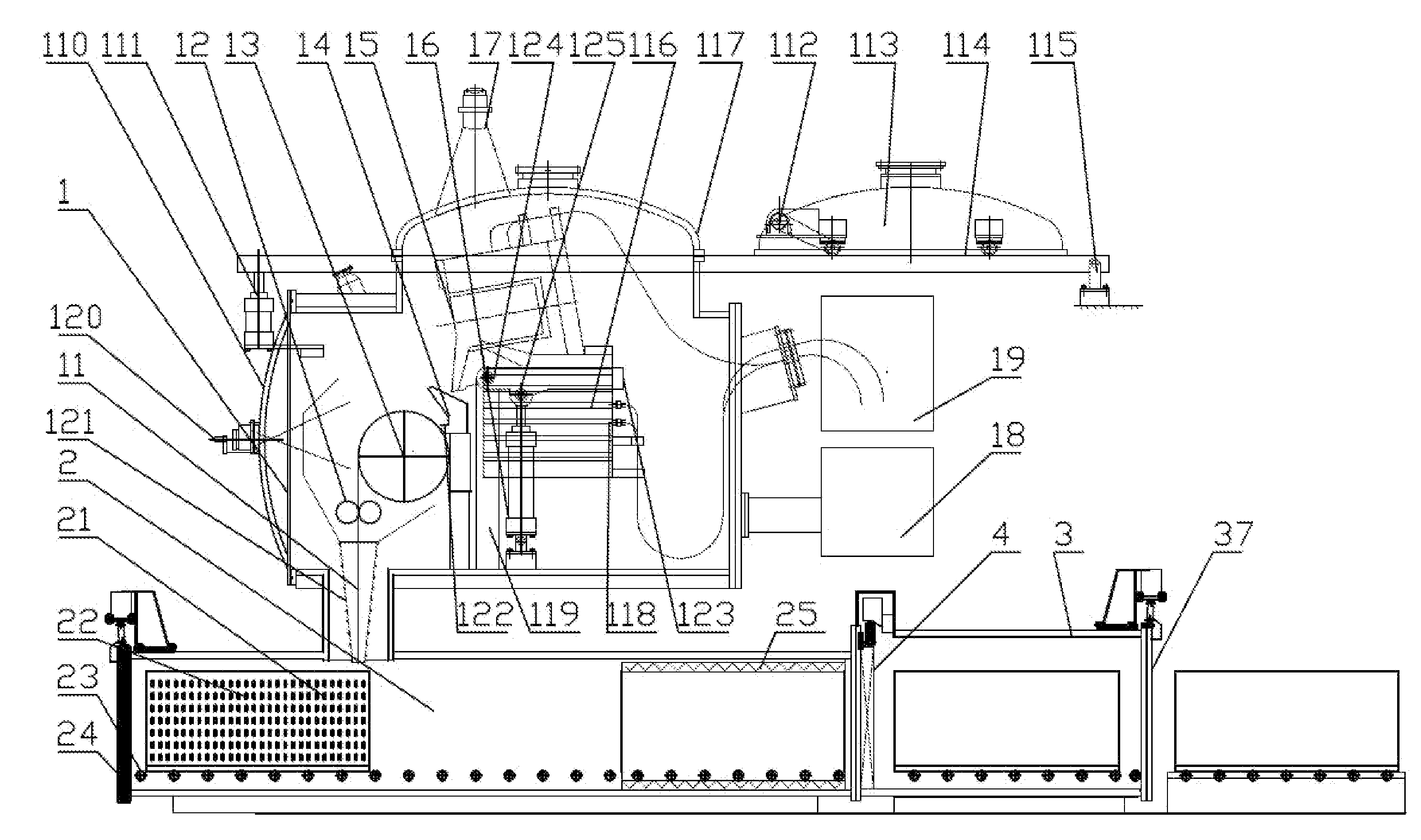
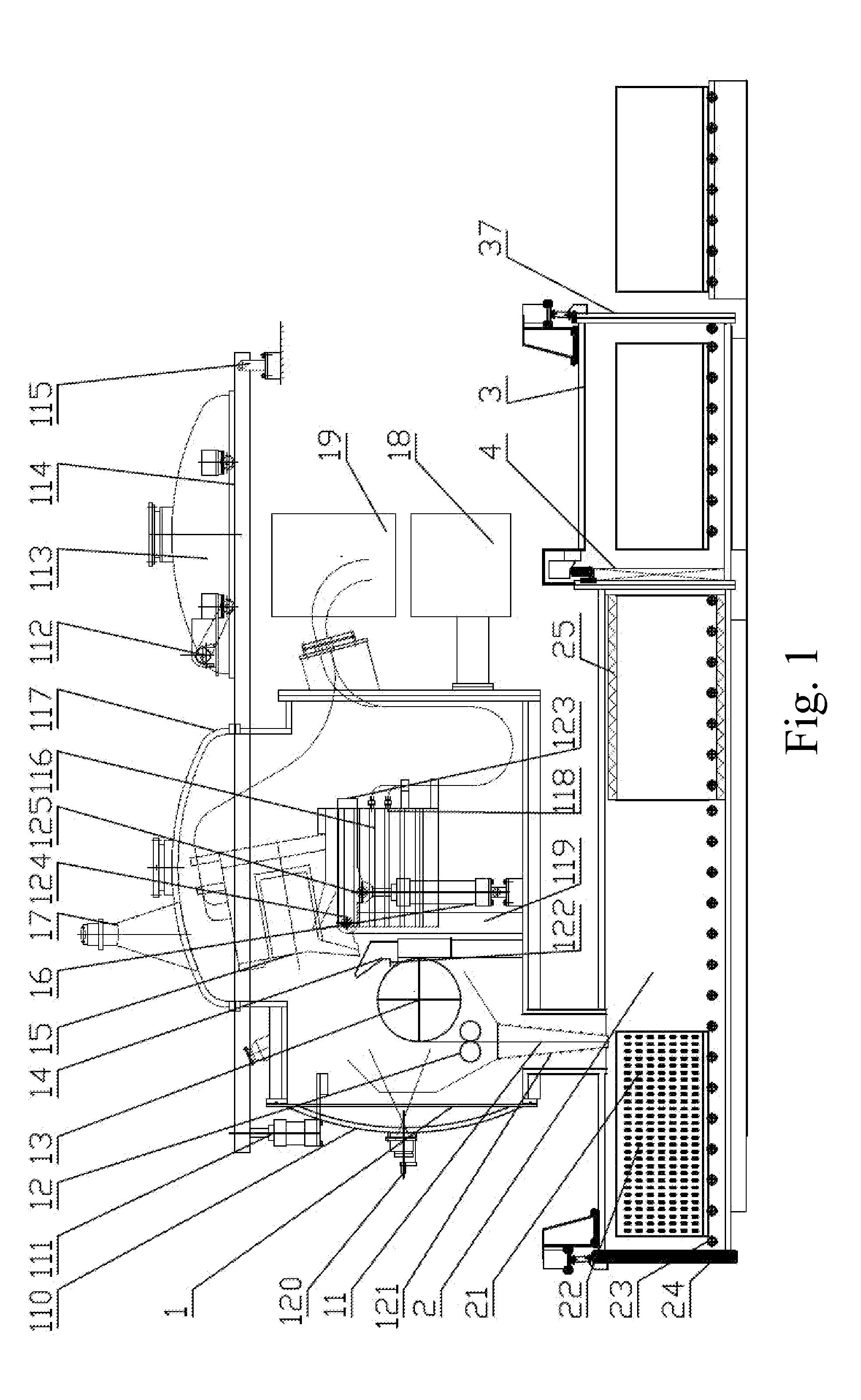
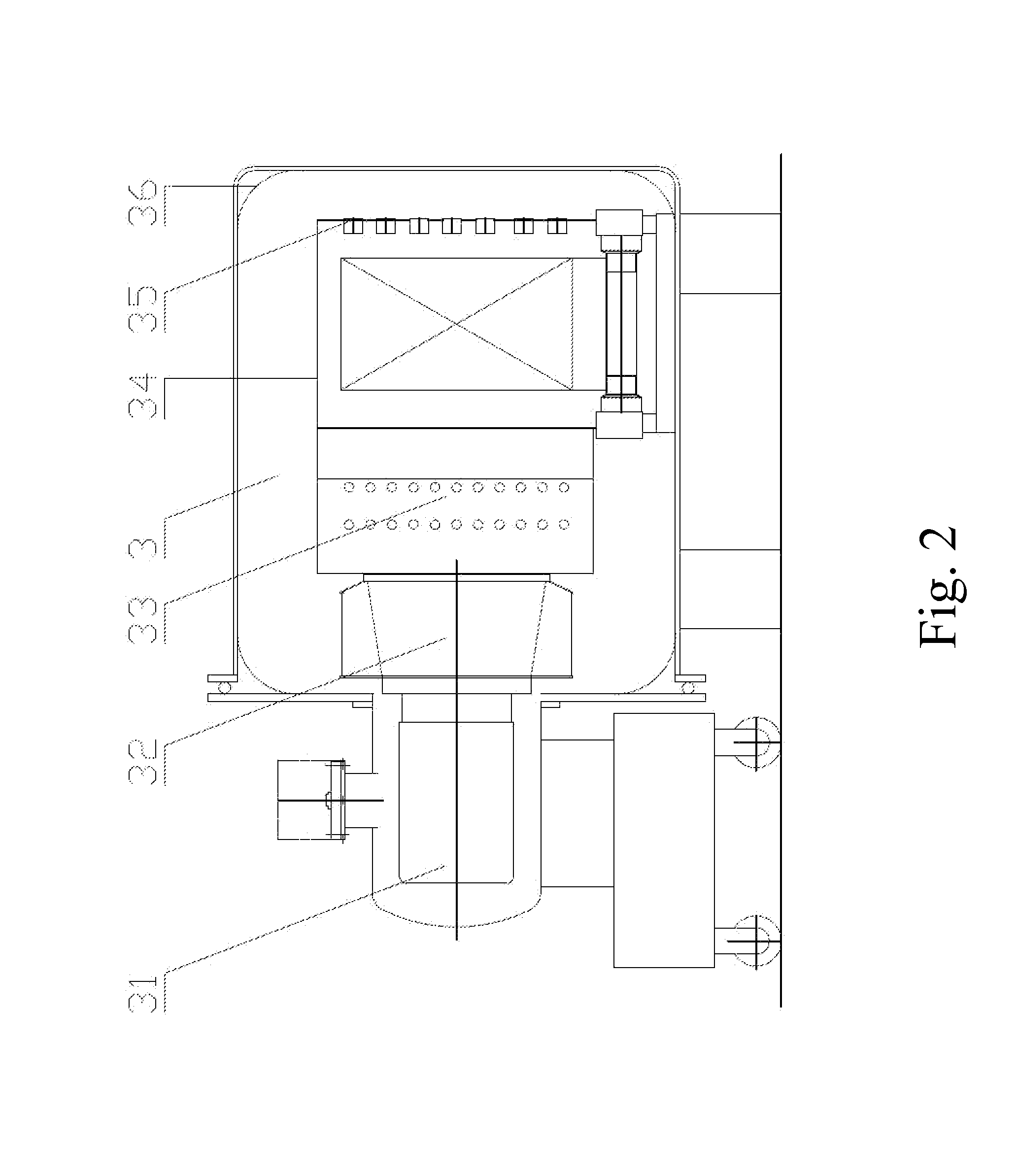
[0022]As shown in FIG. 1, the present invention comprises a vacuum induction melting and strip casting chamber 1, a material receiving heat preservation treatment chamber 2, a cooling chamber 3 and an intra-chamber isolation valve 4, wherein the intra-chamber isolation valve 4 is located between the material receiving heat preservation treatment chamber 2 and the cooling chamber 3, the vacuum induction melting and strip casting chamber 1 is located above the material receiving heat preservation treatment chamber 2, an outlet of a material guiding tube 11 of the vacuum induction melting and strip casting chamber 1 is corresponding to the material receiving heat preservation treatment chamber 2, and the water-cooled electrodes, a vacuum pumping device 18, an inert gas introduction pipeline, a temperature measurement mechanism, a pressure gauge, a vacuum gauge and a safety valve are provided on the vacuum induction melting and strip casting chamber 1. The temperature measurement mechan...


PUM

PropertyMeasurementUnit
pressureaaaaaaaaaa
temperatureaaaaaaaaaa
holding temperatureaaaaaaaaaa

Abstract

A vacuum induction melting and strip casting equipment for rare earth permanent magnetic alloy includes a vacuum induction melting and strip casting chamber, a material receiving heat preservation treatment chamber, a cooling chamber and an isolation valve. The isolation valve is located between the material receiving heat preservation treatment chamber and the cooling chamber, the vacuum induction melting and strip casting chamber is located above the material receiving heat preservation treatment chamber, an outlet of a material guiding tube of the vacuum induction melting and strip casting chamber is corresponding to the material receiving heat preservation treatment chamber. Water-cooled electrodes, a vacuum pumping device, an inert gas introduction pipeline, a temperature measurement mechanism, a pressure gauge, a vacuum gauge and a safety valve are provided on the vacuum induction melting and strip casting chamber. The present invention improves the production efficiency and has high production performance and good consistence.

Description

CROSS-REFERENCE TO RELATED APPLICATIONS[0001]This PCT application is based on application No. 201210442609.5 filed in China on Nov. 8, 2012, the contents of which are incorporated hereinto by reference.BACKGROUND OF THE PRESENT INVENTION[0002]1. Field of Invention[0003]The present invention relates to a vacuum induction melting and strip casting equipment, and more particularly to a vacuum melting and strip casting equipment for melting NdFeB rare earth permanent magnetic alloys and rare earth hydrogen storage alloys.[0004]2. Description of Related Arts[0005]The NdFeB rare earth permanent magnet is widely used to Electronics, electrical appliances, electrical motors and so on, and has a more extensive use. The rare earth hydrogen storage alloy is the negative electrode material of the NiMH battery. It is widely used to electric tools and hybrid electric vehicles and so on, and has a more extensive use.[0006]In the existing NdFeB rare earth permanent magnet manufacturing processes an...

Claims


Application Information

Patent Timeline
Patent Type & Authority Applications(United States)
IPC IPC(8): H01F41/02B22D46/00B22D45/00
CPCH01F41/0266B22D46/00B22D45/00C22C38/00C22C45/02B22D11/0611C22C33/04C22C38/002C22C38/005C01B3/001H01F1/0551H01F1/0571B22D11/1213B22D11/124B22D11/126B22D25/06Y02E60/32
Inventor SUN, BAOYUCHEN, XIAODONG
Owner SHENYANG NORTH VACUUM TECH CO LTD
Learn More