
Data relay device, data transmission device, and network system

a data relay and data technology, applied in data switching networks, instruments, frequency-division multiplexes, etc., can solve the problems of affecting a wide range of development man-hours, affecting the compliance of new protocols, and reducing communication efficiency, so as to improve communication efficiency and avoid enlargement of header information , the effect of simplifying the handling of new protocols

Active Publication Date: 2014-12-18
ORMON CORP
View PDF8 Cites 20 Cited by
  • Summary
  • Abstract
  • Description
  • Claims
  • Application Information

AI Technical Summary

Benefits of technology

This patent is about a device or method that can improve the efficiency of data transmission in industrial networks. The device or method can simplify the routing function and gateway, prevent communication efficiency degradation, and prevent new protocol difficulties. It can generate frame data even if the source node doesn't understand the format specifications of all the protocols. Basically, this invention can make it easier for data to be transmitted in industrial networks.

Problems solved by technology

First, it is necessary that the source node transmitting the message generates the pieces of header information on all the network protocols. Therefore, it is necessary to understand a high level of technical processing and format specifications of all the protocols in a frame generation function of the source node. In the case that the message transmitted from the source node receives a routing abnormality, it is necessary for a person in charge of maintenance to understand the format specifications of all the protocols in order to analyze where and which the abnormality is generated.
Second, with increasing number of kinds of routed networks (encapsulated severalfold), the header information is enlarged to reduce a data area (a payload size in a packet) that can practically be used by a user. In an environment in which the networks are mixed together, a frame size is restricted according to the network having the smallest MTU (Maximum Transmission Unit). For example, for the frame size of about 500 bytes, when the six pieces of 30-byte header information need to be added as described above, about one third of the frame size, namely, 180 bytes are occupied by the header information, which leads to degradation of communication efficiency.
Third, it is difficult to comply with a new protocol. Every time the new protocol emerges, it is necessary to modify the frame generation function of the destination node, and to add the function of generating the header information on the new protocol and the function of the encapsulating the header information on the new protocol. Therefore, development man-hour increases to influence a wide range (a range of the instrument or program to be modified).
However, the above problems cannot be solved even if the technologies disclosed in Patent Document 1 to Patent Document 3 are diverted to the industrial network.

Method used


Image

  • Data relay device, data transmission device, and network system
  • Data relay device, data transmission device, and network system
  • Data relay device, data transmission device, and network system

Examples


examples

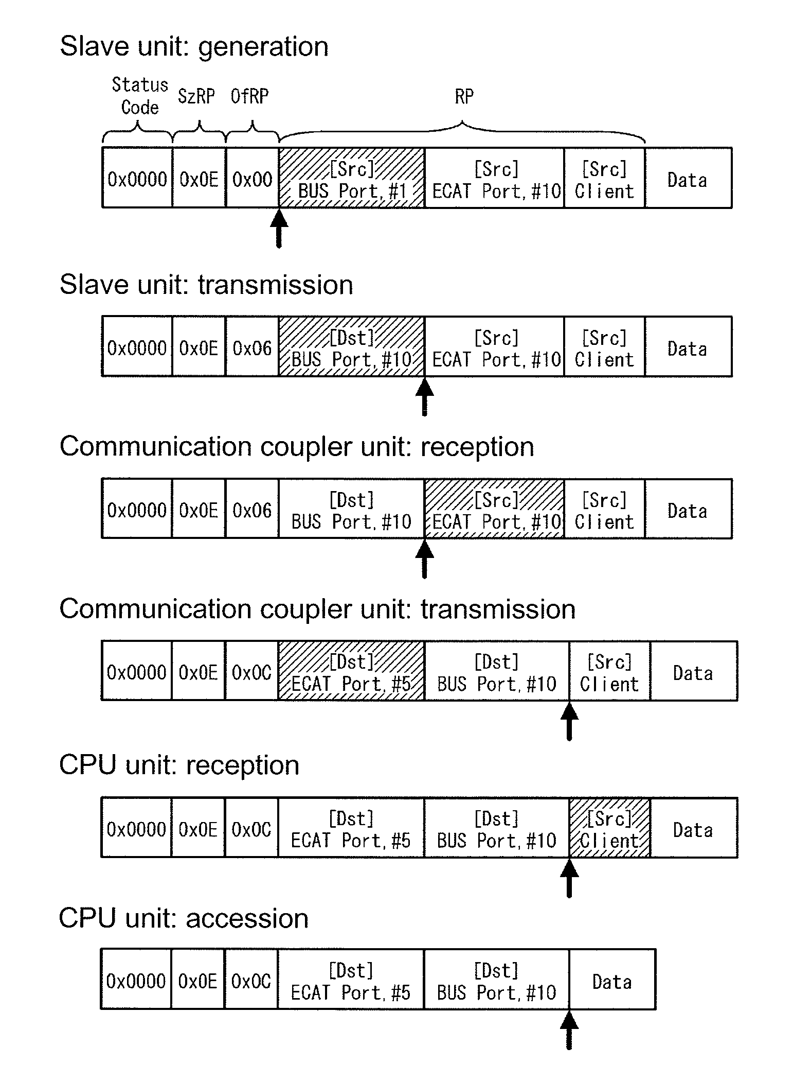
[0069]FIGS. 6 to 8 illustrate specific examples of the gateway (protocol conversion) and routing of the embodiment.

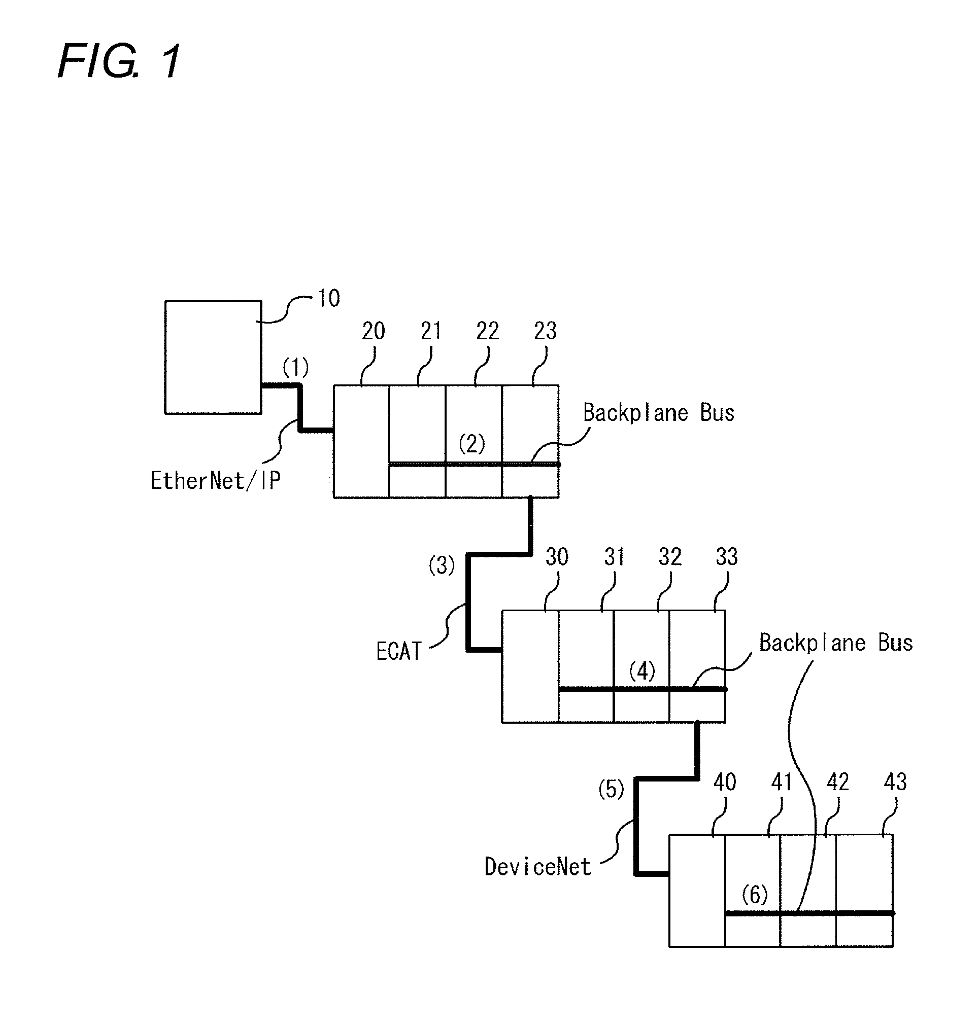
[0070]FIG. 6 illustrates a configuration example of the network system, and the network system includes a CPU unit 600 that is of the source node (data transmission device), a communication coupler unit 610 that is of the relay node (data relay device), and a slave unit 620 that is of the destination node. The CPU unit 600 and the communication coupler unit 610 are connected to each other through EtherCAT (registered trademark), and the node addresses thereof are set to “10” and “5”. The communication coupler unit 610 and the slave unit 620 are connected to each other through a bus, and the node addresses are set to “1” and “10”.

[0071]FIG. 7 illustrates a transition of the common routing information in each node when the CPU unit 600 transmits the message frame. In FIG. 7, “Dst” indicates information on an outward route from the source node to the destination node, and ...

embodiment

Advantage of Embodiment

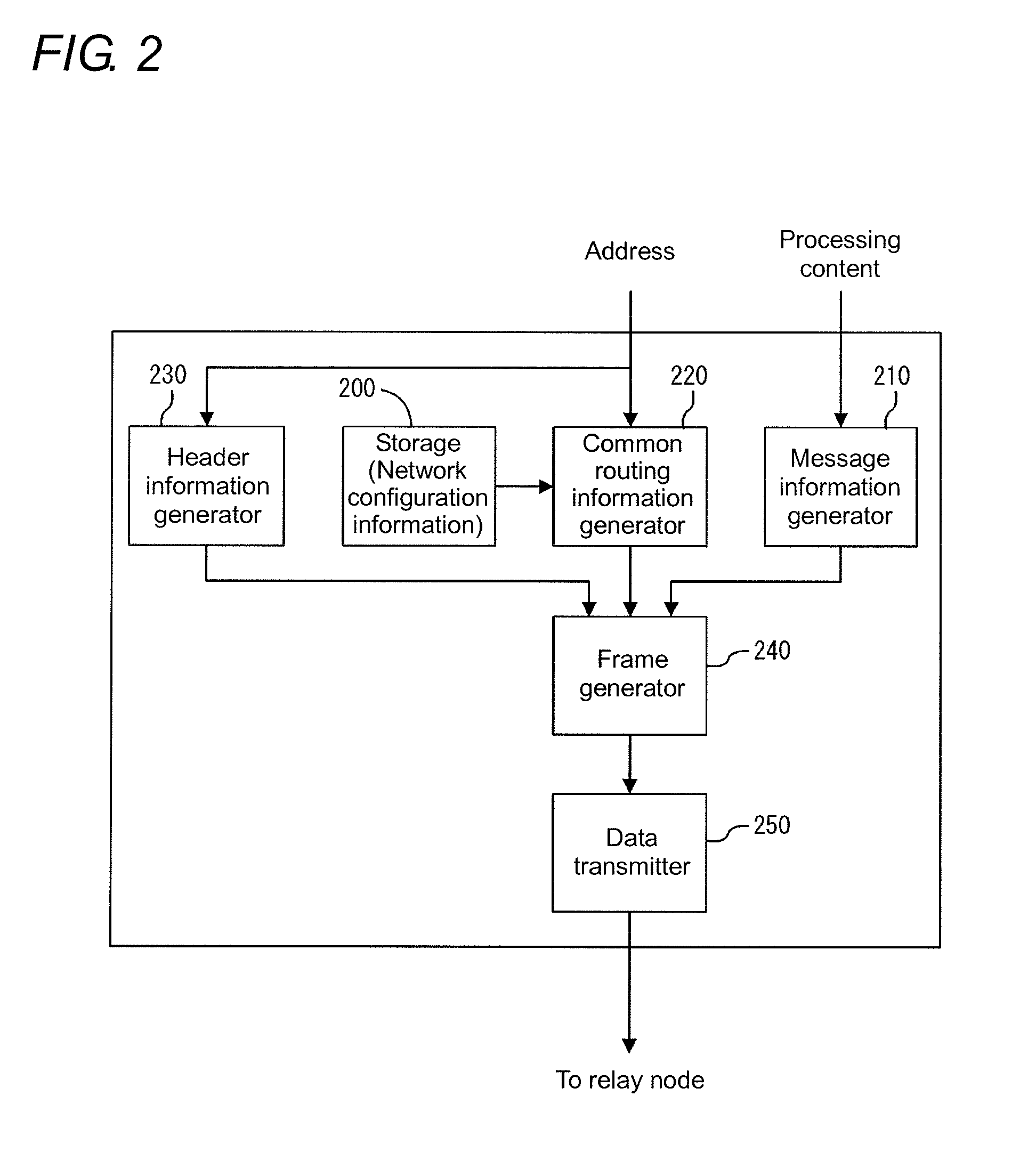
[0075]According to the configuration of the embodiment, it is not necessary for the data transmission device (source node) to generate all the pieces of header information or to understand all the protocol formats, but it is only necessary for the data transmission device to identify the routed nodes from the source node to the destination node. Therefore, the function of the data transmission device can be simplified to reduce the development man-hour.

[0076]According to the above configuration, it is not necessary to perform the multiple encapsulation unlike the conventional technology, but it is only necessary to add the common routing information on the data portion of the frame. The data size of the common routing information can considerably be reduced compared with the case that the pieces of header information are arrayed the number of relay times, so that the data area used by the user can sufficiently be ensured to enhance the practical communication ...


PUM


Abstract

With respect to a routing and a gateway (protocol conversion) in a network system, frame data can simply be generated even if a source node does not understand format specifications of all protocols, communication efficiency degradation caused by an enlargement of header information can be prevented as much as possible, and dealing with a new protocol can be simplified. A source node (data transmission device) transmits “common routing information”, which includes route information identifying all the nodes through which a message frame is routed from an own node to a destination node, while adding the common routing information on the message frame. Each relay node (data relay device) sequentially transfers the message frame while referring to the common routing information to perform identification of a destination, generation of a header, and update of the common routing information.

Description

TECHNICAL FIELD[0001]The present invention relates to a technology of performing a relay between networks having different protocols.BACKGROUND ART[0002]In FA (Factory Automation), an industrial network system controls production facilities (such as motors, robots, and sensors). The industrial network system includes various slave devices each of which performs data collection and control of each production facility installed in a production line and a master device (PLC: Programmable Logic Controller) that centrally controls the slave devices. The industrial network system installed in a production line or a production site is connected to a host computer through an information-system network, and a system manager or an engineer can perform state monitoring or maintenance of each industrial network system with the computer.[0003]Standards such as DeviceNet, CompoNet, and EtherCAT (registered trademark) are well known as a control-system network (field network) that connects the PLC...

Claims


Application Information

Patent Timeline
IPC IPC(8): H04L29/06H04L29/08H04L12/703H04L12/66H04L12/56H04L45/28
CPCH04L69/08H04L12/66H04L67/12H04L69/18H04L45/28H04L45/741H04L45/00H04L12/40006H04L12/4625H04L2012/4026
Inventor UEDA, KIYOTAKANAKAMURA, TOSHIKATSU
Owner ORMON CORP
Learn More