
Cermet Coating and Coated Metal Body Having the Cermet Coating, Method of Producing Cermet Coating, and Method of Producing Coated Metal Body

Inactive Publication Date: 2014-12-18
NAT INST FOR MATERIALS SCI
View PDF4 Cites 2 Cited by
  • Summary
  • Abstract
  • Description
  • Claims
  • Application Information

AI Technical Summary

Benefits of technology

The present invention relates to a new type of cermet coating that has excellent fracture toughness and ductility, making it more durable and resistant to wear and corrosion. Compared to conventional cermet coatings, this new coating has improved characteristics, making it a better choice for protecting metal surfaces. The resulting coated metal body has better durability and performance.

Problems solved by technology

As a result, although cermet coatings such as the WC—Co coating formed by a conventional thermal spraying process have excellent hardness, the fracture toughness was low, and the occurrence of damages such as partial detachment and chipping has been a problem when an instantaneous load is applied locally (for example, Non-Patent Documents 1 and 2).
Further, in the WC—Co coating containing such degradation phases at the time of the process (the η phase and W2C phase described above), since it contains a W—C—Co based material that is excluded from the region of the two-component system with WC and Co as the end components, it is impossible to return to a two-phase state of WC and Co even when the coating is subjected to a heat treatment.
However, although the fracture toughness of the coating obtained by the warm spray process is superior to that of the coatings obtained by a conventional high velocity flame spraying process, it has been far inferior, as compared with that of the sintered bulk body of WC—Co which is produced by a hot press or the like (Non-Patent Documents 3 and 4).
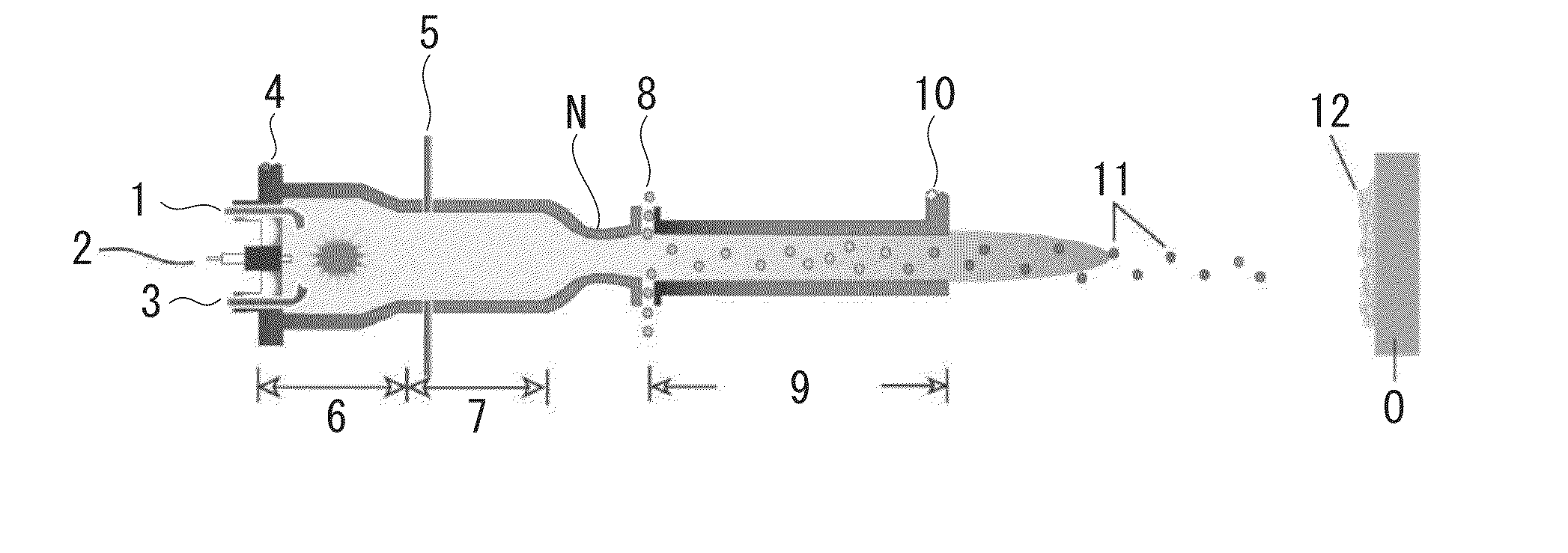
The reason for this is that because the particles fly at a very high speed and collide with the substrate during the process, an extremely large plastic deformation occurs within a Co phase serving as a binder phase, and the crystal structure is disturbed and mostly becomes amorphous.

Method used


Image

  • Cermet Coating and Coated Metal Body Having the Cermet Coating, Method of Producing Cermet Coating, and Method of Producing Coated Metal Body
  • Cermet Coating and Coated Metal Body Having the Cermet Coating, Method of Producing Cermet Coating, and Method of Producing Coated Metal Body
  • Cermet Coating and Coated Metal Body Having the Cermet Coating, Method of Producing Cermet Coating, and Method of Producing Coated Metal Body

Examples


example 1

[0068]The sample which was taken out in Example 1 after the heat treatment was subjected to a structure analysis using a transmission electron microscope.

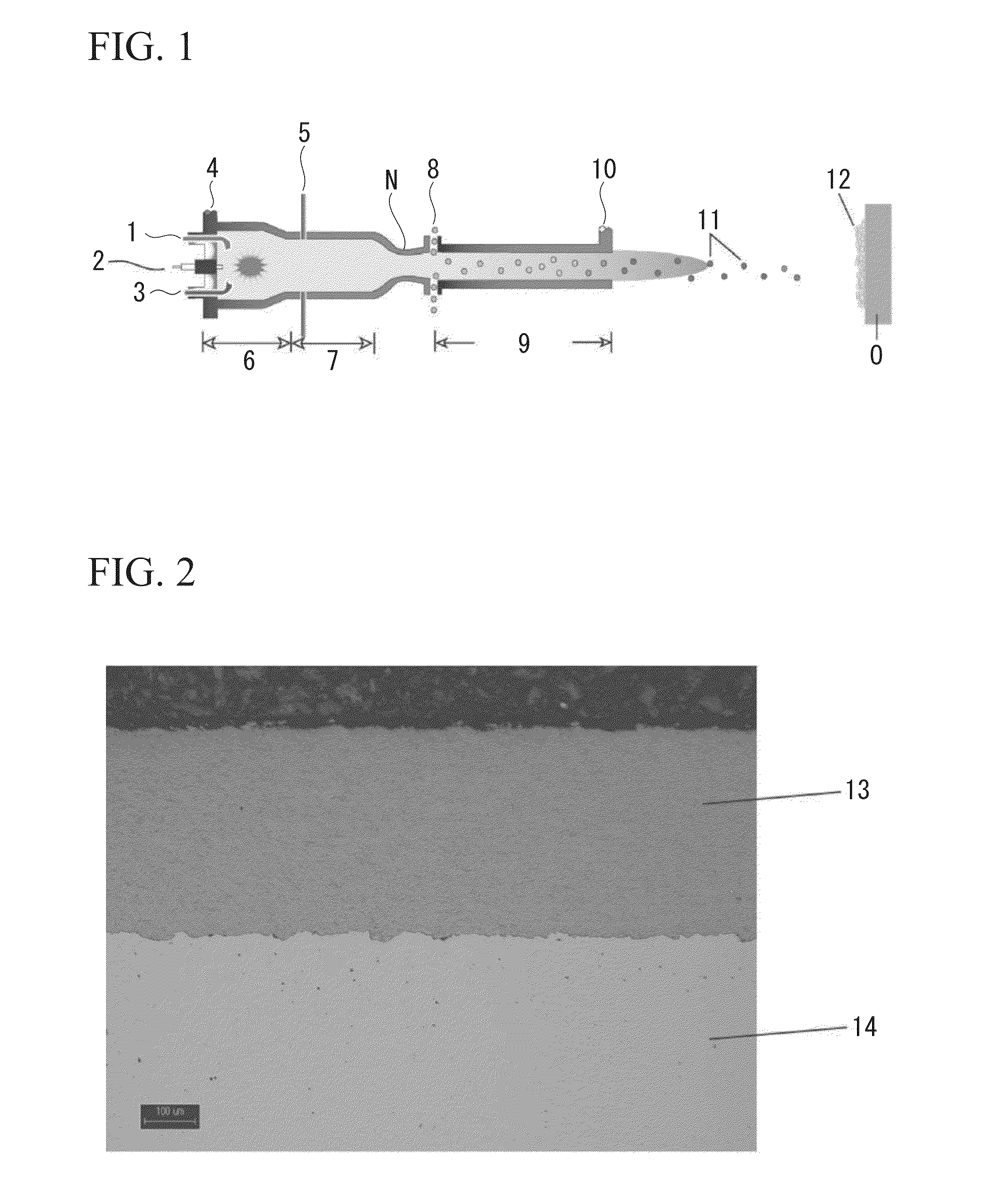
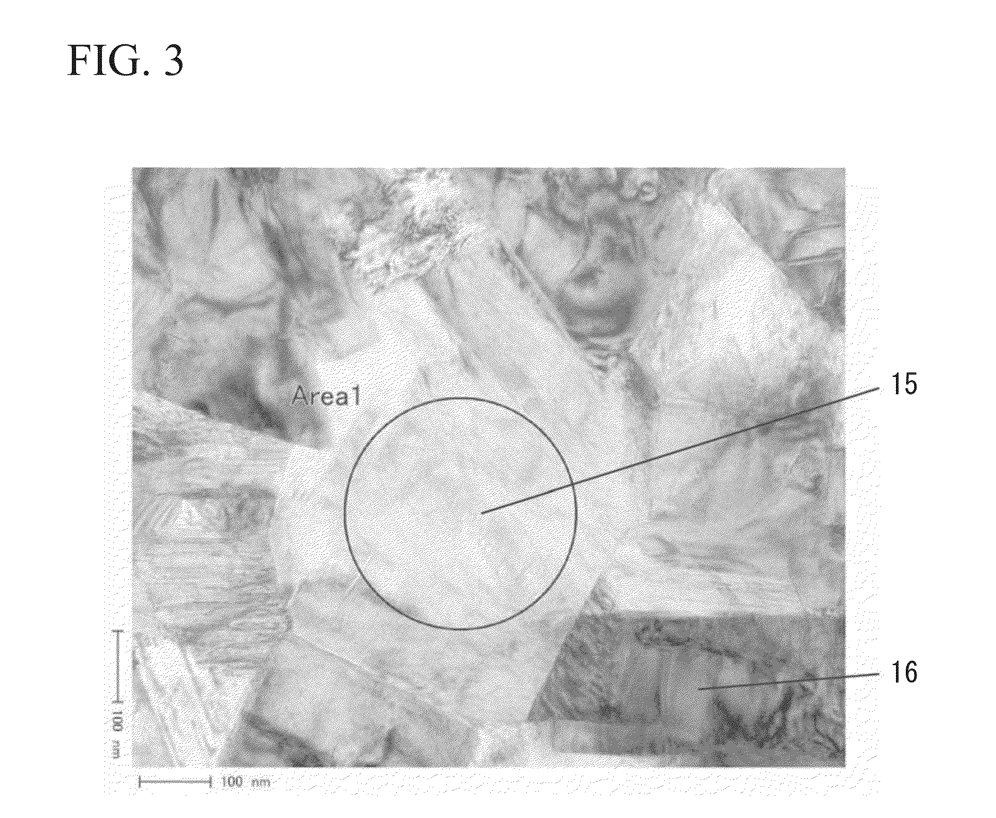
[0069]FIG. 2 shows a cross-sectional photograph of the coating of Example 1 taken by an optical microscope. A coating 13 having a thickness of 400 μm is formed on a carbon steel substrate 14. The structure photograph taken by a transmission electron microscope is shown in FIG. 3. The coating is composed of WC and Co, and the Co portion is composed of a polycrystalline body (in the present figure and in FIGS. 6 and 10, WC is indicated by the reference numeral 15 and Co is indicated by the reference numeral 16). FIG. 4 shows an electron beam diffraction image (selected area electron beam diffraction image) of the Co crystals in an area indicated by a circle in FIG. 3 (Area1). The diffraction pattern due to the crystal structure is confirmed, which indicates that the Co phase is a polycrystalline body. Further, the results of crystal ...


PUM

PropertyMeasurementUnit
Temperatureaaaaaaaaaa
Lengthaaaaaaaaaa

Abstract

A cermet coating includes a hard phase and a binder phase that binds the hard phase,wherein the hard phase includes a carbide phase composed of at least one type of WC and CrC; and the binder phase includes at least one type of metal phase selected from Co, Ni, NiCr, and CoCr, has a structure of a metal polycrystalline body, and is bonded directly to a metal substrate.

Description

TECHNICAL FIELD[0001]The present invention relates to a cermet coating having a novel structure and a method of producing the same, and more specifically, relates to a cermet coating in which hard particles containing a carbide and a metal binder phase that binds them are complexed, and a method of producing the coating. The present invention also relates to a coated metal body having such a coating and a method of producing the same.[0002]Priority is claimed on Japanese Patent Application No. 2012-054561, filed Mar. 12, 2012, the content of which is incorporated herein by reference.BACKGROUND ART[0003]A cermet in which the particles of a hard compound phase such as a carbide and a nitride are bound by a metal phase has been used as a material for modifying the surface properties of substrates. A spraying method has been used conventionally for the formation of a cermet coating. In a spraying method (for example, a high velocity flame spraying process), the raw material powder is me...

Claims


Application Information

Patent Timeline
IPC IPC(8): B32B15/01C23C24/08C09D5/38
CPCB32B15/01C23C24/08C09D5/38C23C24/04C23C30/00Y10T428/12063Y02T50/60
Inventor WATANABE, MAKOTOKURODA, SEIJIKOMATSU, MASAYUKI
Owner NAT INST FOR MATERIALS SCI
Learn More