Method and apparatus for measuring optical properties of particles of a dispersion

a technology of optical properties and dispersion, applied in the field of cytology, can solve the problems of reducing not allowing the detection of other factors, and making the measurement of particle optical properties more difficult, so as to reduce or completely exclude the influence of form factors on the measurement precision, reduce the effect of form factors and reducing the error of form factors

Inactive Publication Date: 2014-12-25
PARTEC GMBH
View PDF2 Cites 0 Cited by
  • Summary
  • Abstract
  • Description
  • Claims
  • Application Information

AI Technical Summary

Benefits of technology

[0015]The object of the invention is to reduce or completely exclude the erroneous influence of form factors on the measurement precision in conventional laser-based flow cytometers. Reducing the form-factor error results in a significantly greater precision of the measurement. It is also a goal of the invention to combine the greater measurement precision with the two scatter light parameters, i.e., particle size and homogeneity, as these cannot be measured with conventional light sources. The device for laser photoexcitation according to the invention avoids the influence of form factors. Compared to conventional light sources with the advantage of excitation with high numerical aperture, the laser excitation permits a much higher light energy density, which results in more precise measurements, because of a better signal-to-noise ratio.

Problems solved by technology

Precise measurement of optical properties of particles is made more difficult, when the particles have very different shapes and sizes.
The technical measurement problem herein lies in the fact that the laser beam hits the morphologically complex particles, which are often structured as very flat, two-dimensional objects, at a right angle to the particle surface, i.e., hits the flat surface, or parallel to the particle surface, i.e., hits the edge.
This results in a “correct” measurement of the particle fluorescence when the laser beam illuminates the surface and an “incorrect” measurement when the laser beam hits the edge of the particle.
This manner of illumination with a large numerical aperture certainly reduces the form-factor influence, but it does not permit the detection of other, often more important, parameters of the cells, such as, forward diffused light (particle size) or sidewise diffused light (homogeneity factor).

Method used


Image

  • Method and apparatus for measuring optical properties of particles of a dispersion
  • Method and apparatus for measuring optical properties of particles of a dispersion
  • Method and apparatus for measuring optical properties of particles of a dispersion

Examples


Embodiment Construction

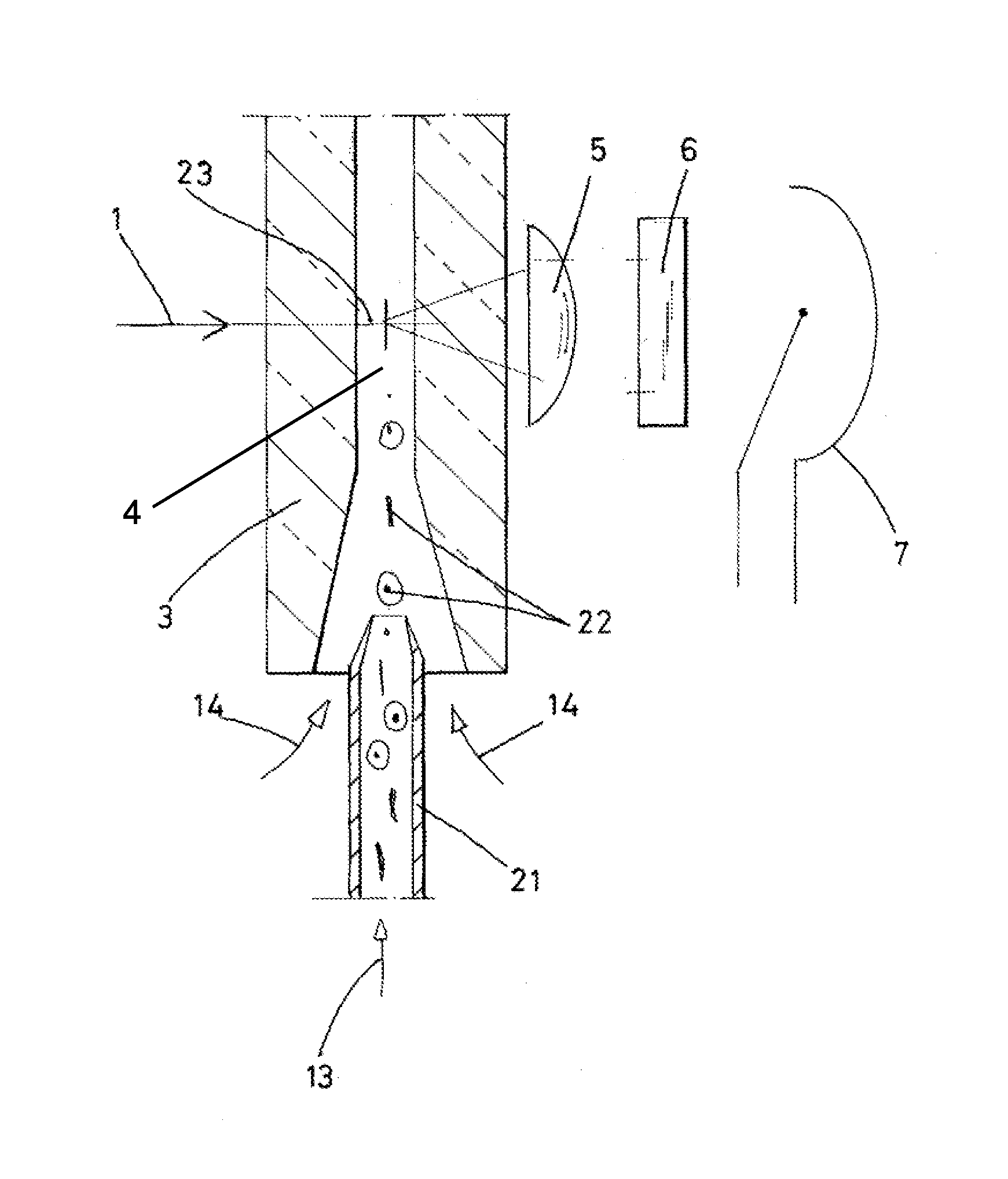
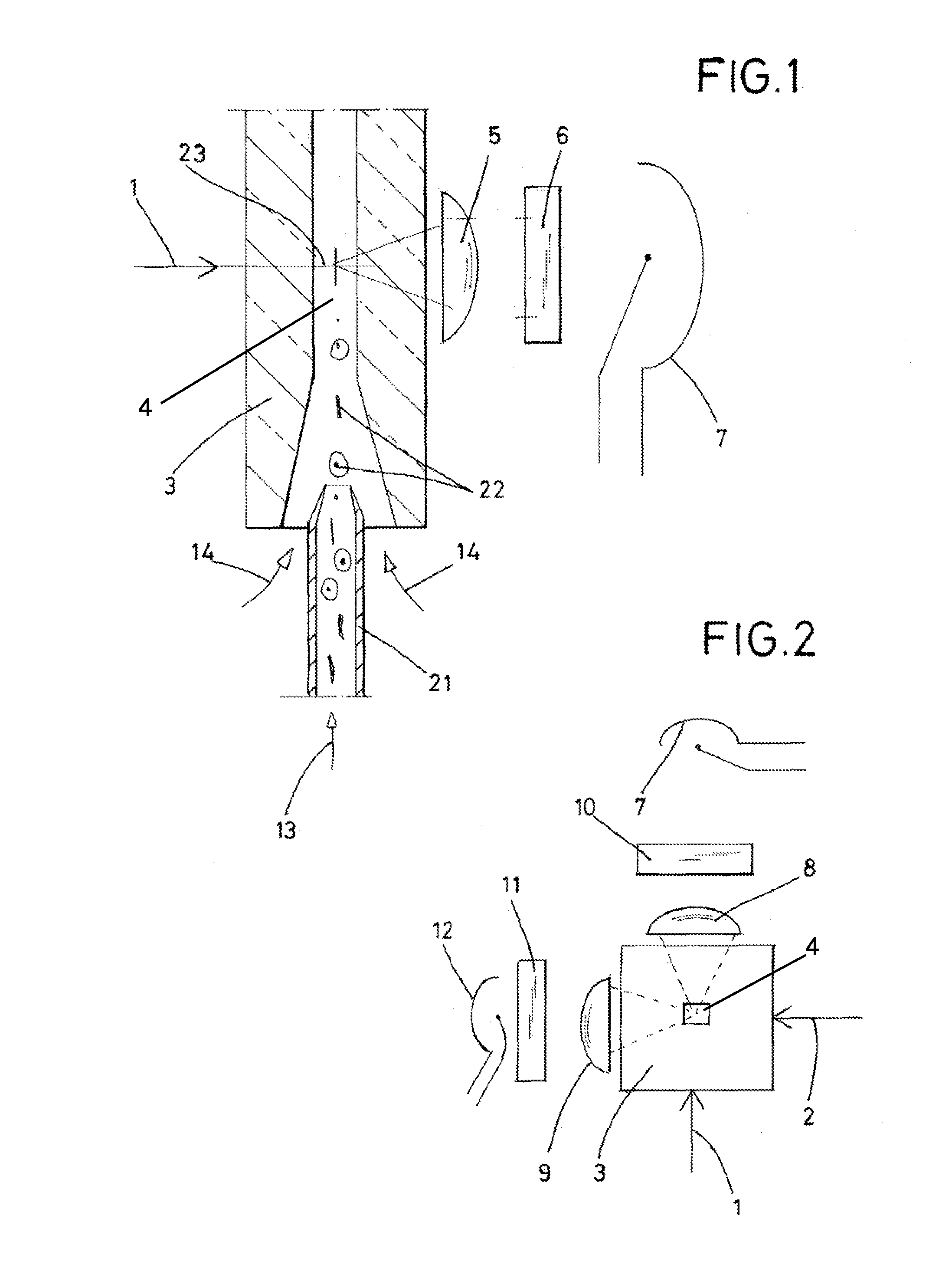
[0023]FIG. 1 is a schematic cross-sectional vertical cut through the cuvette portion of a flow cytometer, showing a flow channel 4, the excitation beam path, using a laser unit that emits a laser beam 1, and the measurement beam path with light-collecting optics in the form of a collecting lens 5, a laser-light blocking filter 6, and a light-sensitive sensor 7, also referred to as a photodetector. The particle dispersion 13 is fed into the flow channel 4 in the measuring cuvette 3 through a narrow tube 21. A plurality of particles P are shown in the flow channel 4.

[0024]A particle-free medium 14 is fed around the particle stream 13, resulting in a centering of the particles when passing the measuring area at 23. The morphologically different particles have no preferred orientation.

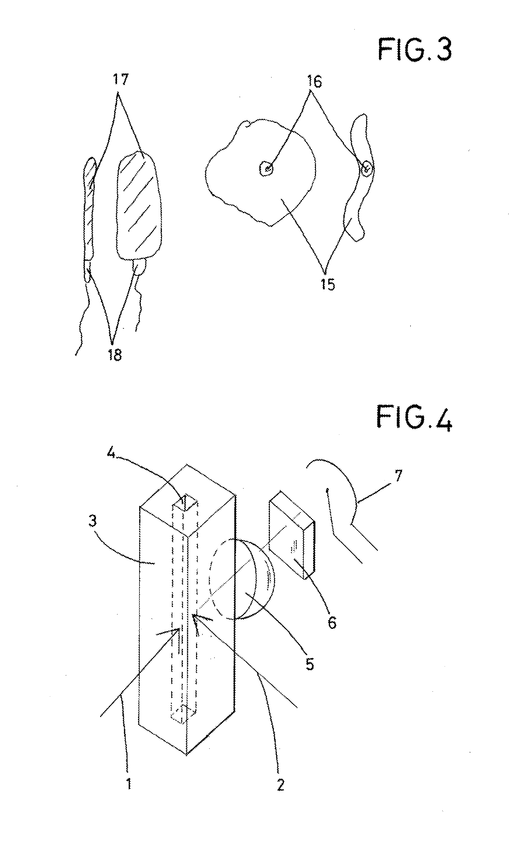
[0025]FIG. 2 and FIGS. 4-6, are schematic illustrations that show a top view or a perspective view of the measuring cuvette 3. These illustrations make clear that, according to the invention, laser photoex...


PUM

PropertyMeasurementUnit
diameteraaaaaaaaaa
angleaaaaaaaaaa
angleaaaaaaaaaa

Abstract

A method for measuring optical properties of particles of a flowable dispersion using a measuring cuvette. As the dispersion flows through the flow chamber of the cuvette, two laser light beams, offset 90 degrees to one another, illuminate the inner chamber of the cuvette and excite fluorescence in a particle. Regardless of the orientation of the particle, the total fluorescing light of the particle provides an accurate measurement of the contents of the cell and balances out form factor errors.

Description

BACKGROUND INFORMATION[0001]1. Field of the Invention[0002]The invention relates to the field of cytology. More particularly, the invention relates to improved cytometric analysis apparatus.[0003]2. Discussion of the Prior Art[0004]Precise measurement of optical properties of a large number of particles of a flowable dispersion, which can be gaseous or liquid, is very important in cytology and when considering technical problems. Currently, flow cytometers allow photometric and fluorescent-optical analysis of several thousand particles per second. Furthermore, devices have been introduced that make it possible to sort the desired particles or cells online based on the previous measurements. Such an arrangement of flow cytometers with downstream cell sorting serves, for example, to separate sperm containing X and Y chromosomes for further use in animal breeding.[0005]For cell sorting, see, e.g., the publication by Bessette, P. H. and Daugherty, P.S. (2004), Flow Cytometric Screening ...

Claims


Application Information

Patent Timeline
Patent Type & Authority Applications(United States)
IPC IPC(8): G01N21/64G01N33/487G01N15/14
CPCG01N21/6486G01N2201/06113G01N33/487G01N15/1434G01N2015/1006G01N21/0303G01N21/47
Inventor GOEHDE, WOLFGANG
Owner PARTEC GMBH
Why Eureka
Try Eureka