Portable Self-Inflating Airborne Wind Turbine System
Inactive Publication Date: 2014-12-25
ANDERSON ALEXANDER ANATOLIY
View PDF22 Cites 27 Cited by
Summary
Abstract
Description
Claims
Application Information
AI Technical Summary
This helps you quickly interpret patents by identifying the three key elements:
Problems solved by technology
Method used
Benefits of technology
Benefits of technology
The present invention is a wind turbine system that is supported by a tethered dirigible filled with lighter-than-air gas. The control system features a feedback system that controls the internal pressure of the blimp and the elevation of the wind turbine. The system also includes a hydrogen generation system to refill the blimp and a hydrogen recovery system to deflate the blimp. The control system also features a feed-forward system to minimize damage from severe weather. The invention has the advantages of being launchable in regions with minimal wind at ground level, avoiding large maintenance costs, reducing noisepollution, and ensuring maximum performance of the airborne wind turbine system. The blimp is lightweight, easily deflated, disassembled, transported, reassembled, and re-inflated.
Problems solved by technology
Firstly, since the condenser, electrolysis system, and compressor are located on the ground, the hydrogen-filled shroud only has to support the weight of the gearbox and electric generator, thereby reducing the required volume of the shroud and thus, the cost.
Secondly, since the compressor only needs to pump hydrogen gas to the blimp, the system requires far less energy than if it were to pump water, which requires a far greater pressure head.
However, if the rotational speed of the wind turbine rotor exceeds a predetermined maximum because of excessive wind speeds, the control system retracts the tether until the blimp reaches a lower altitude, and so lower wind speeds.
Method used
Image
Click on the blue label to locate the original text in one second.
Reading with bidirectional positioning of images and text.
Examples
Embodiment Construction
[0032]The following description details an exemplary configuration of the present invention that may be embodied in many different geometries, forms, and configurations. Therefore, specific structural and functional details disclosed herein are not to be interpreted as limiting, but merely as a representative basis for the set of possible configurations of the present invention.
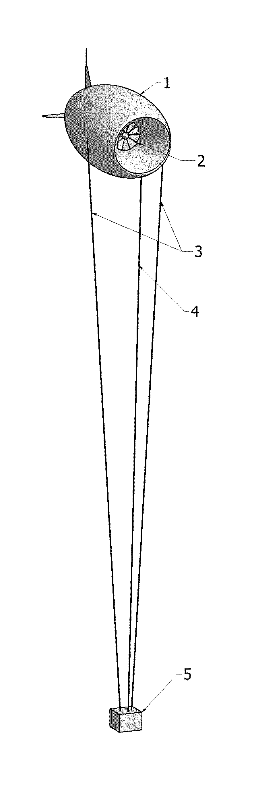
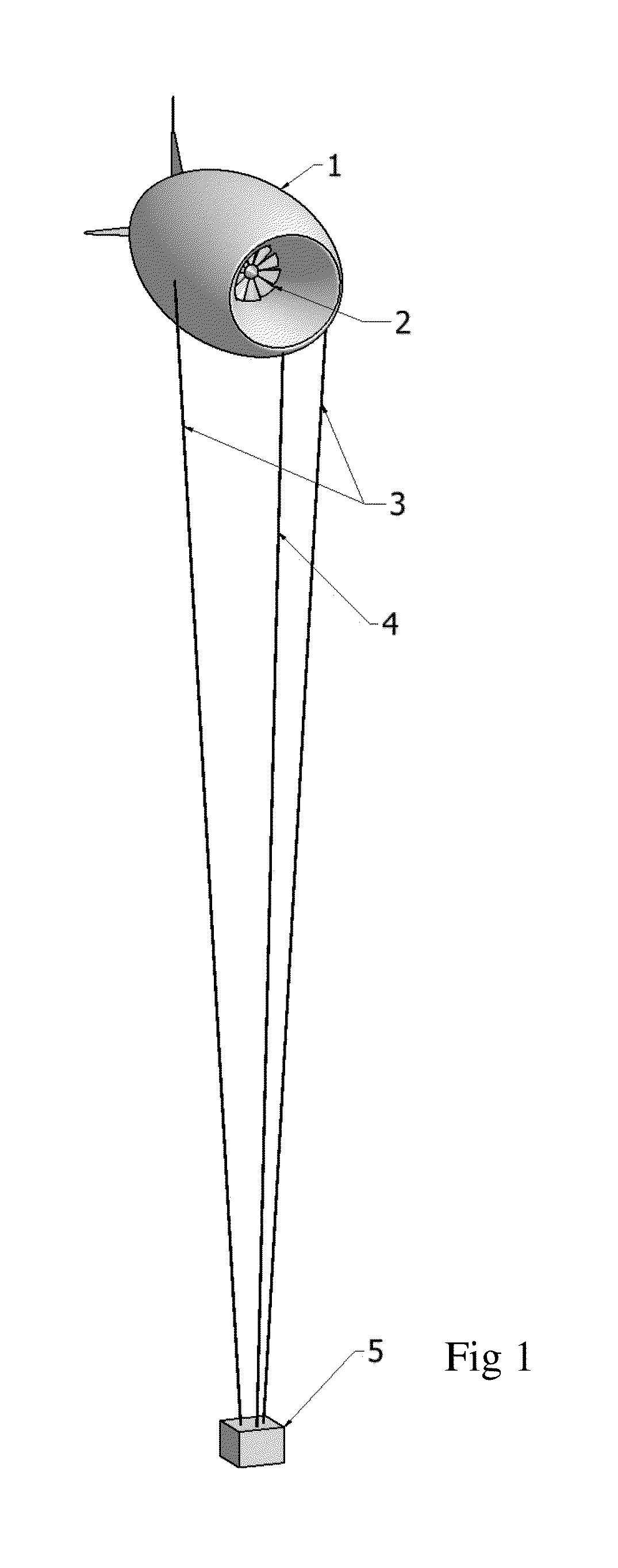
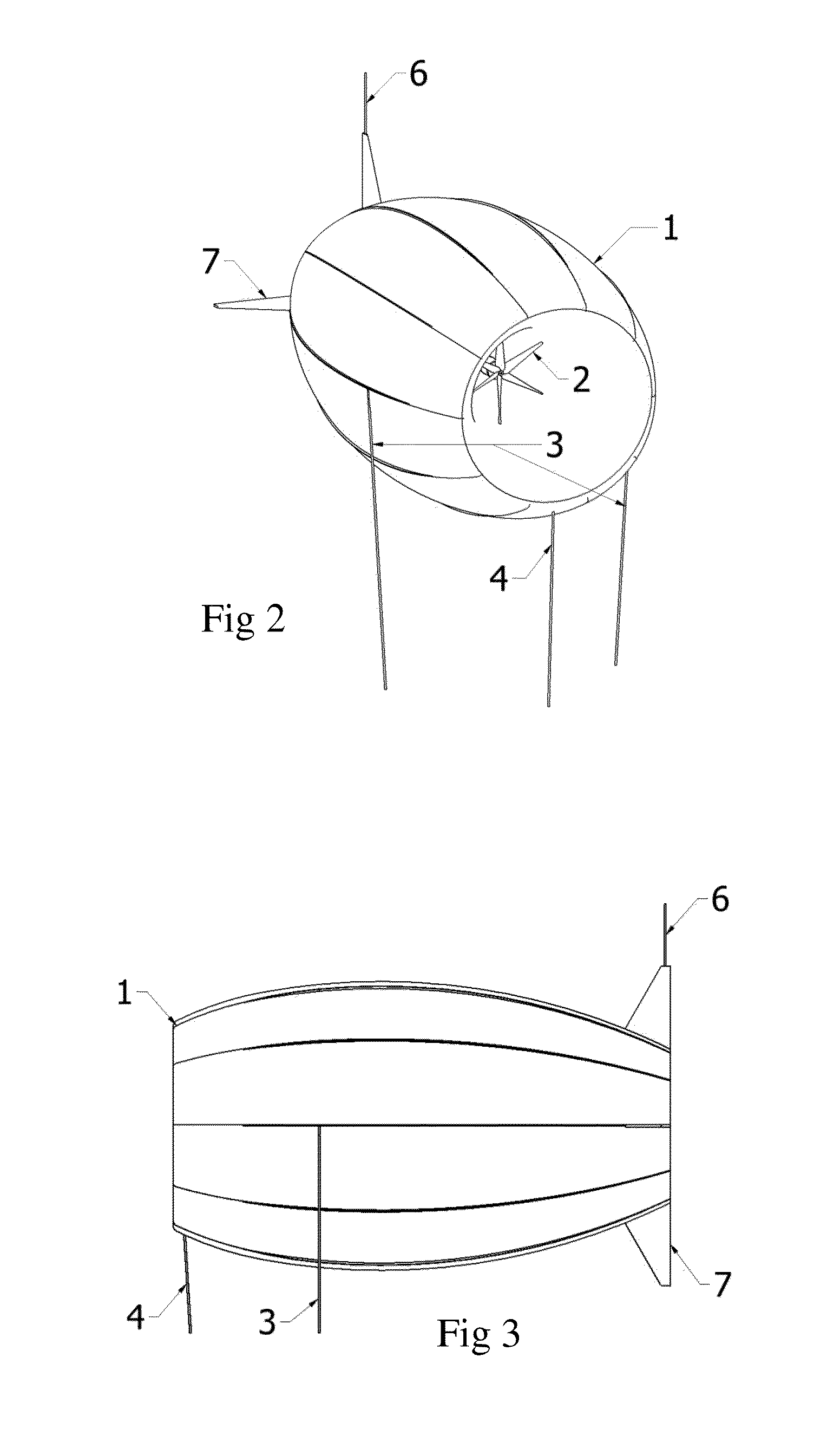
[0033]As depicted in FIG. 1, the present invention consists of the aerodynamic shroud 1 with the geometry of a wind concentrator-diffuser augmenter. The design consists of a venturi nozzle in fluid communication with a diffuser, such that the wind is accelerated as it passes through the flow module. Preferably, the shroud features an optimized geometry to maximize the airflow through the center of the blimp; such a geometry can be determined by either empirical or numerical analysis techniques. The aerodynamic shroud is filled with hydrogen gas so that it is buoyant and supports the weight of the other compon...
PUM
Abstract
A portable airborne wind-energy power conversion system, alone or in a modular array, wherein each portable airborne system comprises tethered airship, hydrogen generation system, hydrogenrecoverysystem, and control system, wherein the tethered airship comprises a self-inflating horizontal-axis wind turbine rotor, an electrical generator, a self-inflating aerodynamic shroud surrounding the wind turbine rotor, and stabilizing fins, wherein the aerodynamic shroud has the geometry of a wind concentrator and diffuser in fluid communication with the wind turbine rotor that is located in the narrowest section of the shroud between the concentrator and diffuser sections of said shroud, wherein the airship is additionally self-deflating and the entire system is collapsible into a volume less than one tenth of its original size, so that the portable airborne system can be easily transported, stored, or relocated, wherein the system can continue to produce usable power, even during the process of self-deflation.
Description
[0001]U.S. PATENT DOCUMENTS.8,395,276March 2013Freda8,393,850March 2013Werle, et al.8,350,403January 2013Carroll8,308,918November 2012Gil, et al8,268,030September 2012Abramov8,253,265August 2012Glass8,246,796August 2012Eikhoff8,202,668June 2012Chiu8,178,990May 2012Freda8,109,711February 2012Blumer, et al8,089,173January 2012Freda8,082,748December 2011Matsuo, et al7,939,960May 2011Kim7,938,623May 2011Cairo7,830,033November 2010Meller7,804,186September 2010Freda7,786,610August 2010Potter7,709,973May 2010Meller7,723,861May 2010Meller7,615,138November 2009Davidson7,602,077October 2009Ferguson7,582,981September 2009Meller7,335,000February 2008Ferguson7,317,261January 2008Rolt7,129,596October 2006Macedo7,218,011May 2007Hiel, et al.7,109,598September 2006Roberts7,008,711March 2006Pondo, et al6,890,410May 2005Sullivan6,781,254August 2004Roberts6,766,982July 2004Drucker4,491,739January 1985Watson4,450,364May 1984Benoit4,433,552February 1984Smith4,350,897September 1982Benoit4,350,896September...
Claims
Application Information
Patent Timeline
Application Date:The date an application was filed.
Publication Date:The date a patent or application was officially published.
First Publication Date:The earliest publication date of a patent with the same application number.
Issue Date:Publication date of the patent grant document.
PCT Entry Date:The Entry date of PCT National Phase.
Estimated Expiry Date:The statutory expiry date of a patent right according to the Patent Law, and it is the longest term of protection that the patent right can achieve without the termination of the patent right due to other reasons(Term extension factor has been taken into account ).
Invalid Date:Actual expiry date is based on effective date or publication date of legal transaction data of invalid patent.

