
Hydrocarbon Conversion

a technology of hydrocarbon conversion and conversion process, applied in mechanical equipment, mechanical equipment, thermal non-catalytic cracking, etc., can solve the problems of reducing the ability of the expansion zone to produce work, and reducing the production efficiency of the expansion zon

Active Publication Date: 2014-12-25
EXXONMOBIL CHEM PAT INC
View PDF0 Cites 60 Cited by
  • Summary
  • Abstract
  • Description
  • Claims
  • Application Information

AI Technical Summary

Benefits of technology

The invention is a hydrocarbon conversion process that involves compressing and heating a mixture of saturated hydrocarbon molecules, transferring the heat to a second mixture, and reacting the second mixture with the expanded effluent to produce a third mixture. The process can also include indirectly transferring heat from the second mixture to the expanded effluent through a catalytic hydrogen transfer reaction. The technical effects of the invention include increased efficiency and flexibility in hydrocarbon conversion, as well as improved power production and utilization.

Problems solved by technology

Although utilizing a higher air temperature in the burner's air supply is generally beneficial, the ultimate air temperature is limited by the amount of expansion in the gas turbine's expansion zone.
Less expansion generally provides burner air of a higher temperature, but also lessens the expansion zone's ability to produce work.
Undesirably, utilizing the steam-cracked product as a gas turbine fuel represents the loss of valuable olefinic products.

Method used


Image

  • Hydrocarbon Conversion
  • Hydrocarbon Conversion
  • Hydrocarbon Conversion

Examples


example 1

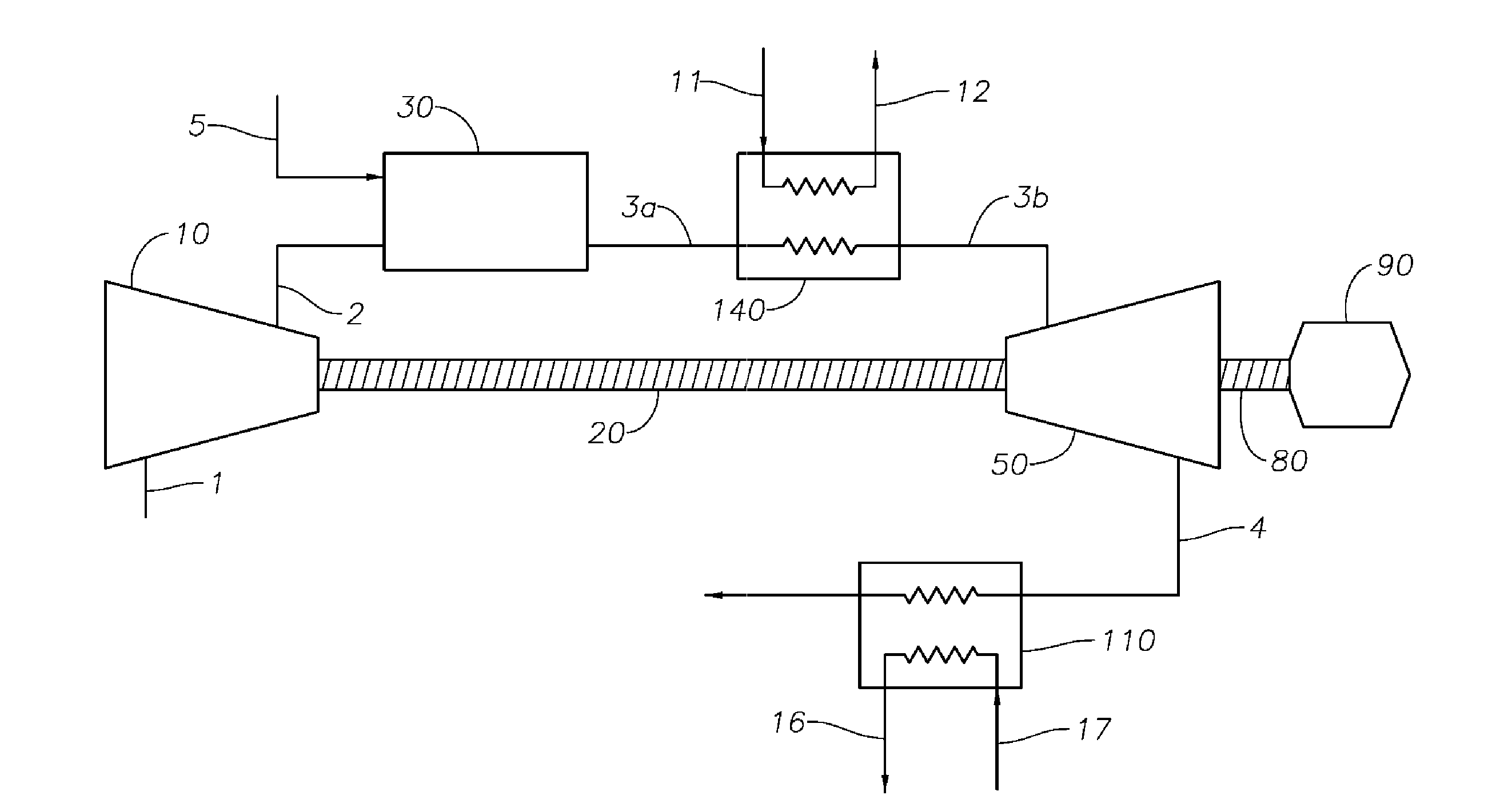
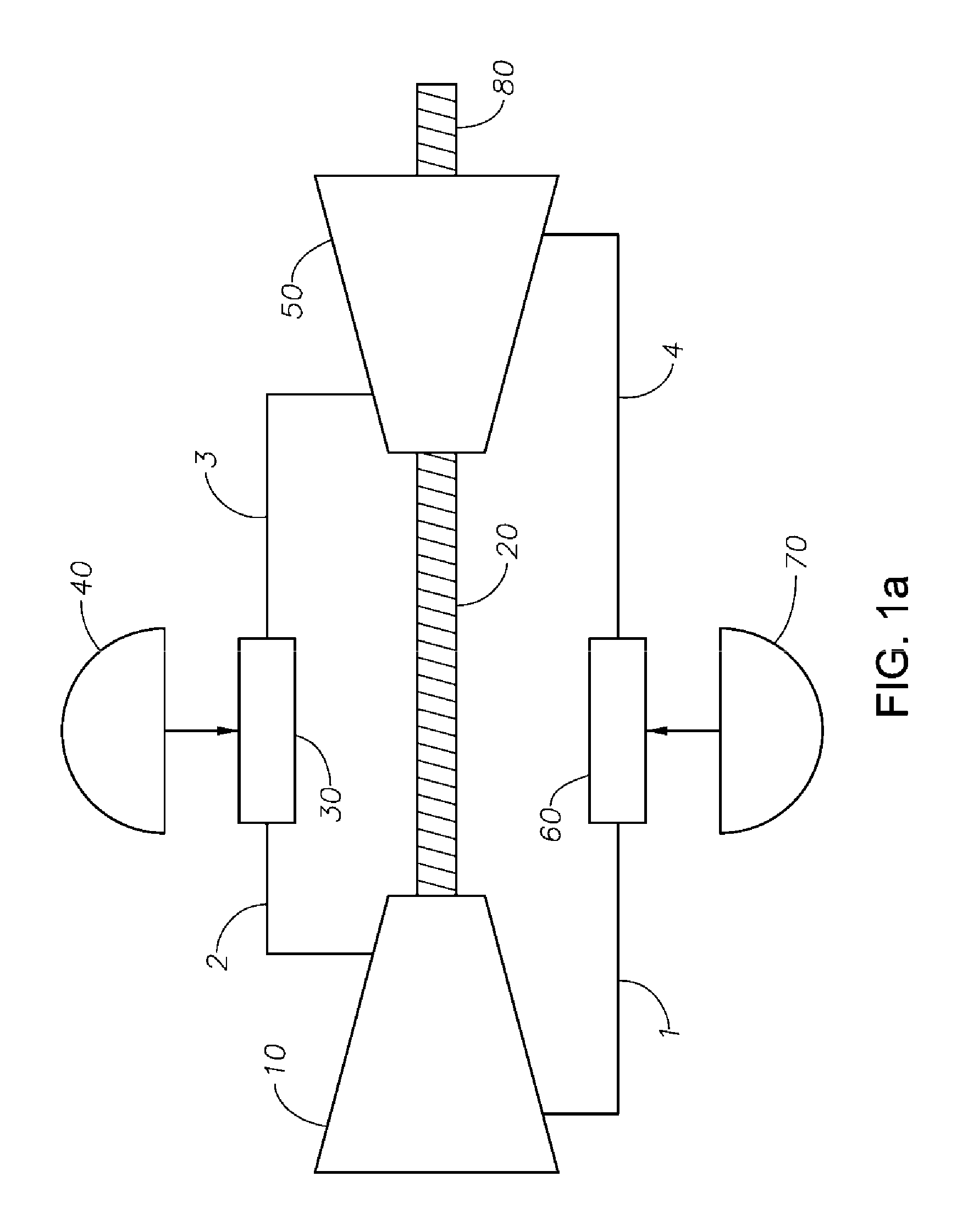
[0099]The following simulation is conducted, with reference to FIG. 3a. A working fluid comprising ≧99.0 wt. % of ambient air based on the weight of the working fluid is conducted to the compression zone 10 via conduit 1 at a rate of 500 kg / s. The ambient air has a temperature of 300° K (T1) and a pressure of 1 bar absolute (P1). The compressed air conducted away from zone 10 via conduit 2 has a temperature T2 and a pressure of 5 bar absolute (P2). Using the relationship T2=T1*(P2 / P1)(γ−1) / γ, with γ=1.4 (approximate value for air), T2 is approximately 475° K.

[0100]10.9 kg / s of natural gas fuel is conducted to combustion chamber 30, where the fuel and a portion of the compressed air are combusted to produce heated compressed air having a temperature T3 and a pressure P3. The combustion produces a power dQ / dt of 478×106 J / s. A value for T3 of approximately 1426° K is obtained using the relationship dQ / dt=Cp*(dm / dt)(T3−T2).

[0101]The heated compressed air is conducted to reaction zone 1...

example 2

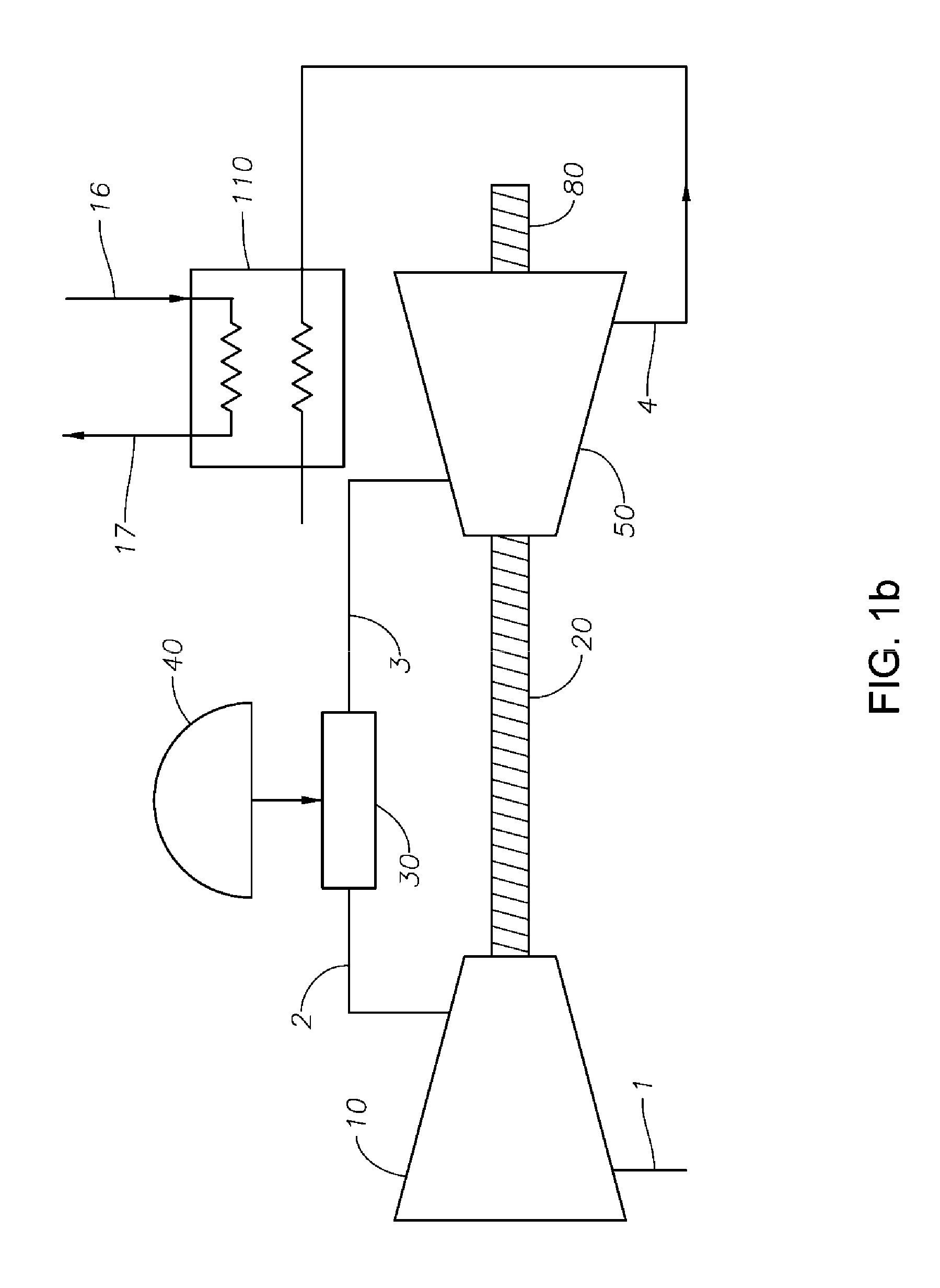
[0105]The following simulation is conducted, with reference to FIG. 5. A working fluid comprising ≧99.0 wt. % of ambient air based on the weight of the working fluid is conducted to the compression zone 10 via conduit 1 at a rate of 500 kg / s. The ambient air has a temperature of 300° K (T1) and a pressure of 1 bar absolute (P1). The compressed air conducted away from zone 10 via conduit 2 has a temperature T2 and a pressure of 5 bar absolute (P2). A value for T2 of approximately 475° K is obtained using the relationship T2=T1*(P2 / P1)(γ−1) / γ, with γ=1.4 (approximate value for air).

[0106]8.8 kg / s of natural gas fuel is conducted to combustion chamber 30, where the fuel and a portion of the compressed air are combusted to produce heated compressed air having a temperature T3 and a pressure P3. The combustion produces a power dQ / dt of 364×106 J / s, and T3 is approximately 1200° K. P3 is approximately 5 bar absolute.

[0107]The heated compressed air is conducted to expansion zone 50 via con...


PUM

PropertyMeasurementUnit
temperatureaaaaaaaaaa

Abstract

The invention relates to hydrocarbon conversion processes, to equipment useful in such processes, to the products of such hydrocarbon conversion processes and the use thereof, and to the use of energy derived from such processes.

Description

PRIORITY CLAIM[0001]This application claims priority to and the benefit of U.S. Provisional Application No. 61 / 838,992, filed Jun. 25, 2013 and EP 13179760.7, filed Nov. 13, 2013.FIELD OF THE INVENTION[0002]The invention relates to hydrocarbon conversion processes, to equipment useful in such processes, to the products of such hydrocarbon conversion processes and the use thereof, and to the use of energy derived from such processes.BACKGROUND OF THE INVENTION[0003]Conventional hydrocarbon conversion processes can be utilized for producing relatively high-value hydrocarbons, e.g., light olefins such as ethylene, propylene, butylene, etc., from relatively low-value hydrocarbon-containing feeds, such as methane, ethane, propane, naphtha, gas oil, crude oil, heavy oil, etc. One such conventional process is steam cracking, a form of thermal pyrolysis where a feed comprising substantially-saturated hydrocarbon is combined with steam, the steam-hydrocarbon mixture then being pyrolysed in o...

Claims


Application Information

Patent Timeline
Patent Type & Authority Applications(United States)
IPC IPC(8): C07C5/35C07C4/04C07C5/32
CPCC07C5/35C07C4/04C07C5/325C01B3/24C10G31/06C01B2203/1241C01B2203/84F02C3/20C10G35/00C10G49/00C10G9/00
Inventor DAVIS, STEPHEN MARKMERRIFIELD, MARK L.KUECHLER, KEITH H.STARCHER, LOREN K.
Owner EXXONMOBIL CHEM PAT INC
Learn More