Two-terminal electronic devices and their methods of fabrication

a technology of electronic devices and terminals, applied in the direction of thermoelectric devices, solid-state devices, radiation controlled devices, etc., can solve the problems of increasing the high cost of pvd and cvd apparatuses, and high cost of electronic device fabrication, so as to improve device mechanical properties, less expensive processing, and improve device storage time and stability in operation

Inactive Publication Date: 2015-01-15
FANTASY SHINE LTD +1
View PDF16 Cites 35 Cited by
  • Summary
  • Abstract
  • Description
  • Claims
  • Application Information

AI Technical Summary

Benefits of technology

[0005]Two-terminal electronic devices, such as two-terminal photodetectors, photovoltaic devices, electroluminescent devices and high density arrays comprising two-terminal devices that can be fabricated with minimal or no photoresist-dependent patterning, are provided. The struct...

Problems solved by technology

These techniques can be expensive and time-consuming.
PVD and CVD apparatuses are expensive and their use increases the costs of electronic device fabrication.
Moreover, stress that is developed during deposition process and/or patterning process is often significant and leads to low manufacturing yield.
Plasma-enhanced chemical vapor deposition (PECVD) process used for deposition of a thick...

Method used


Image

  • Two-terminal electronic devices and their methods of fabrication
  • Two-terminal electronic devices and their methods of fabrication
  • Two-terminal electronic devices and their methods of fabrication

Examples


example 1

UV Detector

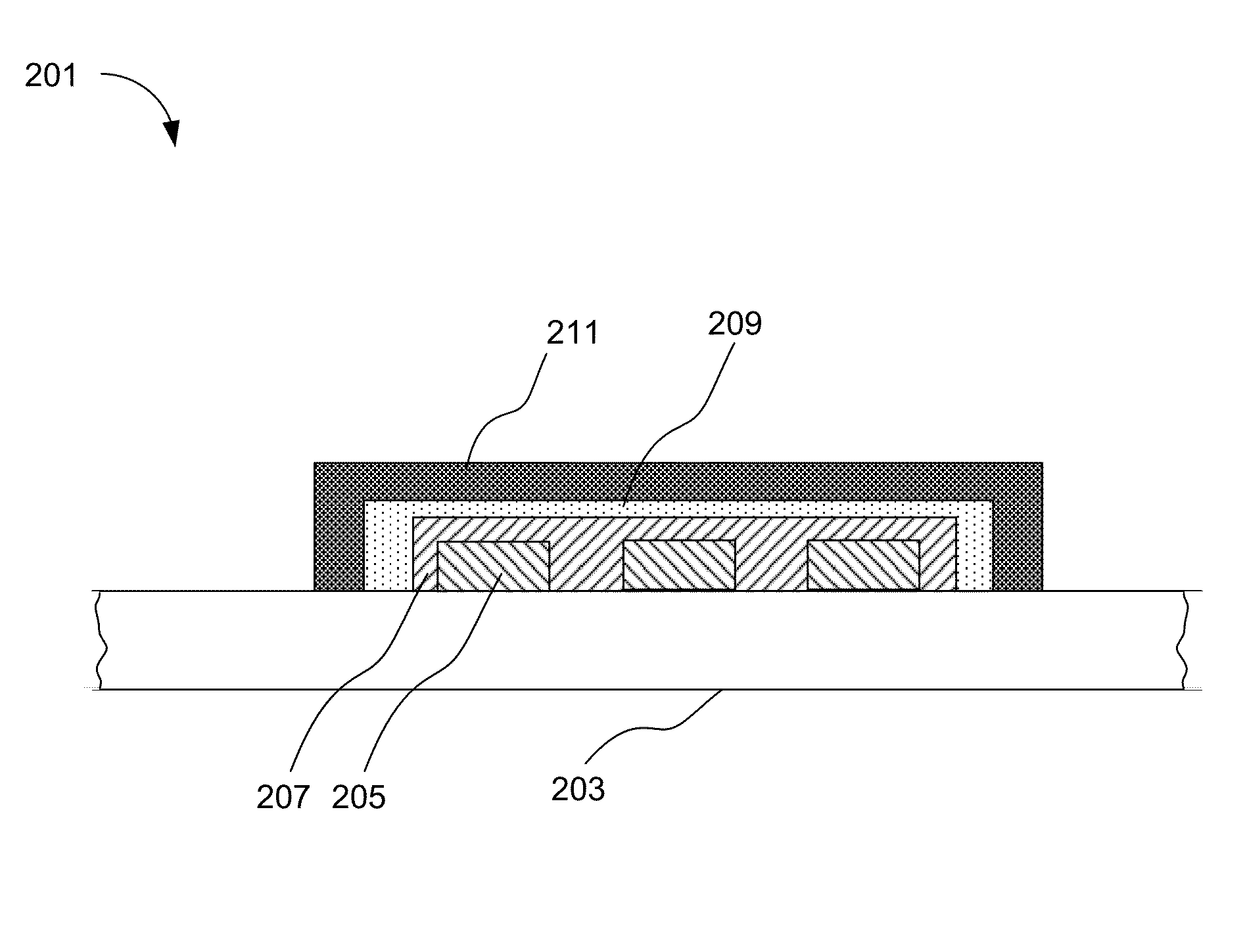
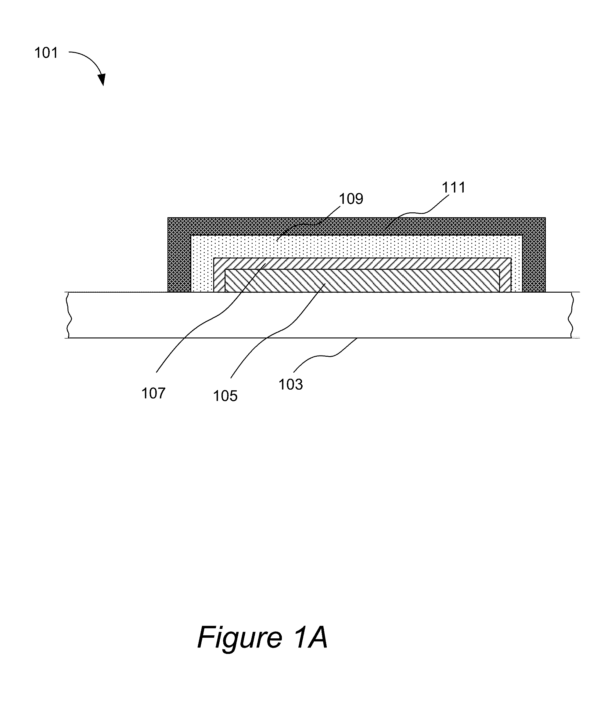
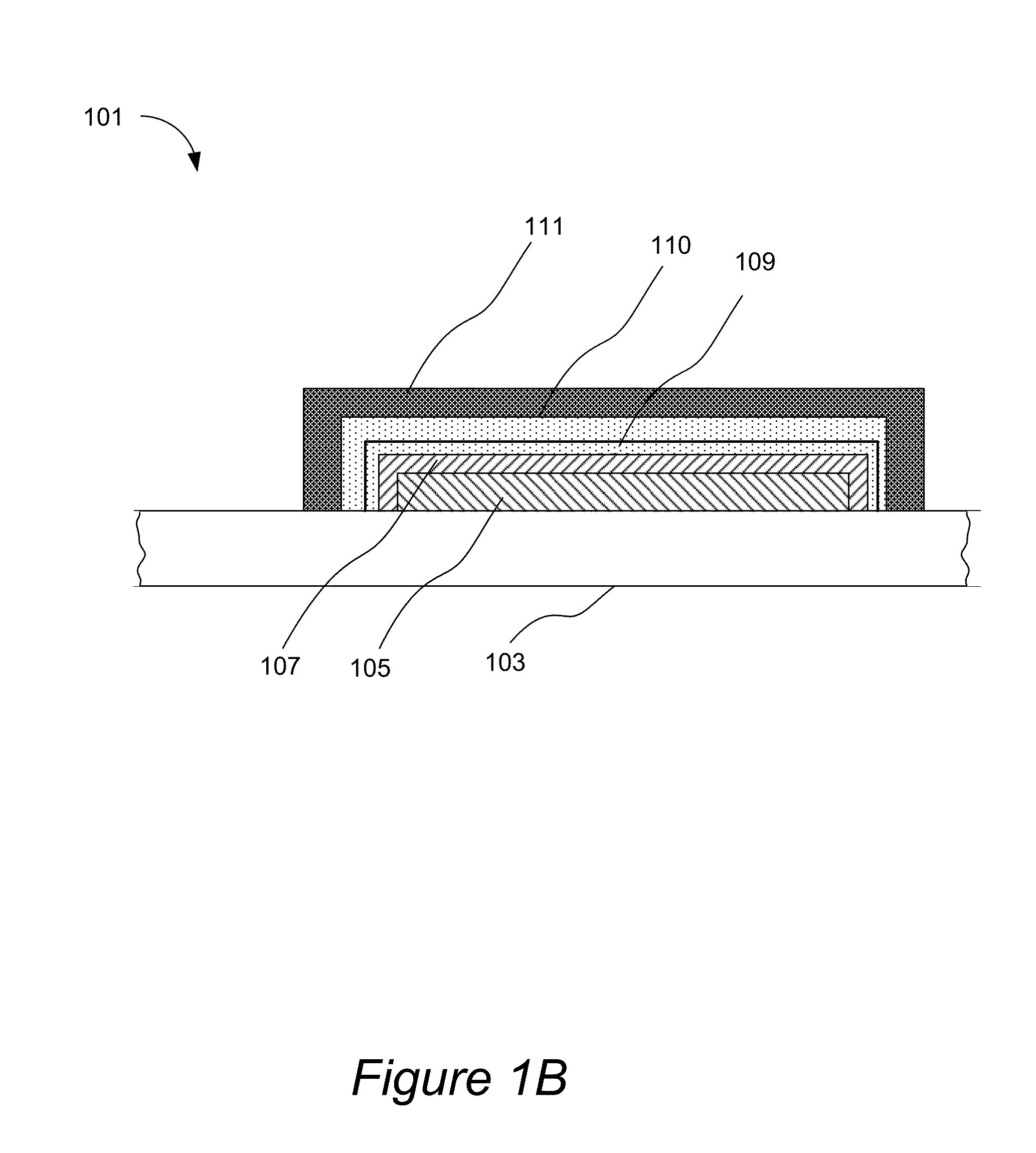
[0153]In accordance with one example, a UV detector is provided which has the following structure: M / MO / p-type semiconductor / TCO. In some embodiments the metal, M, is Ti, Ta, Zn, In, Sn, or Ga. The I-layer is a metal oxide layer, where the oxide is formed in a self-aligned manner from the top portion of the first electrode by oxidation which can be achieved by annealing the metal in O2 environment, by treating the metal with O2 plasma, by anodization of the metal, or by heating the metal and contacting it with H2O2, or by a combination of the processes listed above In those cases where metal oxide is formed by a dry process (e.g., O2 plasma, heating in O2-contained environment) or by a wet process (e.g., by anodization, or hydrogen peroxide treatment), the surface of the oxide may be cleaned, e.g., with a water rinse and is then dried. A p-type organic or inorganic layer or both in stack or in a blend form is then deposited on the clean dry surface of metal oxide. Example...

example 2

Broadband NIR / Visible Light Photodetectors and Photovoltaic Cells

[0157]When narrow energy gap semiconductor is used in the semiconductor layer, absorption is shifted to longer wavelengths. IR and / or visible light photodetectors can be built. These devices can also be used as photovoltaic devices.

[0158]The bottom electrode layer is a metal layer. In some embodiments the metal is Ti, Ta, Zn, In, Sn, or Ga. The I-layer is a metal oxide layer, where the metal is the same metal as used for the first electrode. The semiconductor layer can be organic or inorganic p-type semiconductor, or an organic / inorganic blend, or a stack. Examples of suitable materials include PPV, MEHPPV, P3HT, PCPDTBT, PDDTT, CuO, PbS, CuInSe, CuInS, CuInGaSe. Such devices can be used as single detectors but are especially suitable for detector arrays due to simplicity of their manufacturing process and high process yield. In the array devices, the sensor pixel can be defined by the bottom metal pattern, the remaini...

example 3

Visible / Near-Infrared (NIR) Detector Array with an Unpatterned Semiconductor Layer

[0163]In this example, the bottom electrode was made with a 100 nm thick ITO or a 100 nm thick Ag layer by DC sputtering, which was then patterned by lithography to define individual devices. Titanium oxide I-layer was formed by DC sputtering of titanium metal layer with nominal thickness of 10 or 50 Anstrong, and then the unpatterned Ti layer was oxidized to TiO2 by thermal oxidation at 200° C. A blend polymer semiconductor comprising either PTB7:PC70BM or PCPDTBT:PC70BM (1:2 weight ratio, purchased from 1-Materials, Dorval, Quebec, Canada) was coated from a blend solution at room temperature over the I-layer and was then dried at 150° C. for 30 minutes to remove residual solvent. Toluene and chlorobenzene were used for as solvent for this study. The thickness of this layer (referred to as a sensing layer or the first semiconductor sub-layer) was approximately 200 nm. It is an organic semiconductor wi...


PUM

PropertyMeasurementUnit
Band gapaaaaaaaaaa
Work functionaaaaaaaaaa
Ratioaaaaaaaaaa

Abstract

Two-terminal electronic devices, such as photodetectors, photovoltaic devices and electroluminescent devices, are provided. The devices include a first electrode residing on a substrate, wherein the first electrode comprises a layer of metal; an I-layer comprising an inorganic insulating or broad band semiconducting material residing on top of the first electrode, and aligned with the first electrode, wherein the inorganic insulating or broad band semiconducting material is a compound of the metal of the first electrode; a semiconductor layer, preferably comprising a p-type semiconductor, residing over the I-layer; and a second electrode residing over the semiconductor layer, the electrode comprising a layer of a conductive material. The band gap of the material of the semiconductor layer, is preferably smaller than the band gap of the I-layer material. The band gap of the material of the I-layer is preferably greater than 2.5 eV.

Description

CROSS-REFERENCE TO RELATED APPLICATIONS[0001]This application is a continuation-in-part of U.S. patent application Ser. No. 13 / 467,539, filed May 9, 2012, by Yu et al., which is a continuation of U.S. patent application Ser. No. 13 / 015,013, filed Jan. 27, 2011, now U.S. Pat. No. 8,193,594, issued Jun. 5, 2012, by Yu et al., which is a continuation of U.S. patent application Ser. No. 11 / 801,735, filed May 9, 2007, now U.S. Pat. No. 7,898,042, issued Mar. 1, 2011, by Yu et al., which claims benefit of U.S. Provisional Application No. 60 / 857,750 filed Nov. 7, 2006, titled “Metal-insulator-metal (MIM) devices and their methods of fabrication” naming Gong et al. as inventors, which applications are herein incorporated by reference for all purposes. U.S. patent application Ser. No. 13 / 467,539 is a continuation-in-part of U.S. patent application Ser. No. 11 / 983,205, filed Nov. 6, 2007, now U.S. Pat. No. 8,222,077, issued Jul. 17, 2012, by Gong et al., which claims benefit of U.S. Provision...

Claims


Application Information

Patent Timeline
IPC IPC(8): H01L27/32H01L27/30H01L31/0224H01L31/0336H01L31/032H01L31/0312H01L31/0272H01L31/0352H01L31/18H01L33/00H01L33/06H01L33/34H01L33/26H01L33/42H01L51/42H01L51/44H01L51/56H01L51/52H01L51/50H01L27/146
CPCH01L51/5206H01L33/42H01L27/14696H01L51/56H01L33/26H01L31/1884H01L33/34H01L33/06H01L31/0272H01L27/14669H01L33/005H01L31/0312H01L51/442H01L31/18H01L2933/0016H01L51/4293H01L31/035218H01L27/32H01L27/14665H01L31/0322H01L27/14683H01L31/0324H01L31/022475H01L51/5234H01L31/0336H01L51/502H01L27/307H01L27/14676H01L31/072H01L31/046Y02E10/50H10K39/32H10K39/36H10K59/10H10K85/141H10K85/324H10K85/342H10K10/29H10K30/30H10K50/115H10K50/171H10K50/18H10K50/17H10K2102/321
Inventor YU, GANGSHIEH, CHAN-LONGCHEN, ZHAO
Owner FANTASY SHINE LTD
Why Eureka
Try Eureka