Inverter surge-resistant insulated wire

a technology of insulated wire and inverter, which is applied in the direction of insulated conductors, flat/ribbon cables, cables, etc., can solve the problems of low voltage decay due to connection cables, high surge voltage, and high steep voltage rise, and achieve excellent insulation properties and high partial discharge inception voltage.

Active Publication Date: 2015-01-22
ESSEX FURUKAWA MAGNET WIRE LLC
View PDF6 Cites 33 Cited by
  • Summary
  • Abstract
  • Description
  • Claims
  • Application Information

AI Technical Summary

Benefits of technology

[0028]The inverter surge-resistant insulated wire of the present invention has high partial discharge inception voltage and is excellent in both insulation property at a high temperature and thermal aging resistance property.
[0029]Other and further features and advantages of the invention will appear more fully from the following description, appropriately referring to the accompanying drawings.

Problems solved by technology

In particular, an output pulse occurred due to a high-speed switching device, such as an IGBT, is high in steep voltage rise.
Accordingly, even if a connection cable is short, the surge voltage is high, and voltage decay due to the connection cable is also low.
In the meantime, partial discharge deterioration is a complicated phenomenon in which an electrical-insulation material undergoes, for example, molecular chain breakage deterioration caused by collision with charged particles that have been generated by partial discharge of the insulating material, sputtering deterioration, thermal fusion or thermal decomposition deterioration caused by local temperature rise, and chemical deterioration caused by ozone generated due to discharge.
However, the resins of commonly used resin varnishes generally have a dielectric constant between 3 and 5, and none of the resins have particular low dielectric constant.
Further, upon considering other properties (heat resistance, solvent resistance, flexibility, and the like) required from the enamel layer, it is not necessarily possible to select actually a resin having a low dielectric constant.
However, to thicken the in enameled layer, the number of times for passing through a baking furnace increases in a production process thereof, whereby making a film composed of copper oxide on a copper conductor surface thicker, this in turn, causing lowering in adhesion between the conductor and the backed enamel layer.
However, this method has a drawback that the solvent of the varnish is not completely vaporized and remains in the enamel layer as voids.

Method used


Image

  • Inverter surge-resistant insulated wire
  • Inverter surge-resistant insulated wire

Examples


example 1

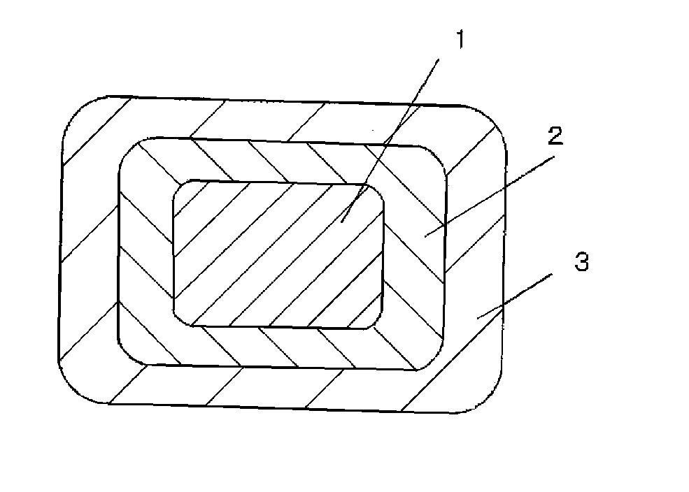
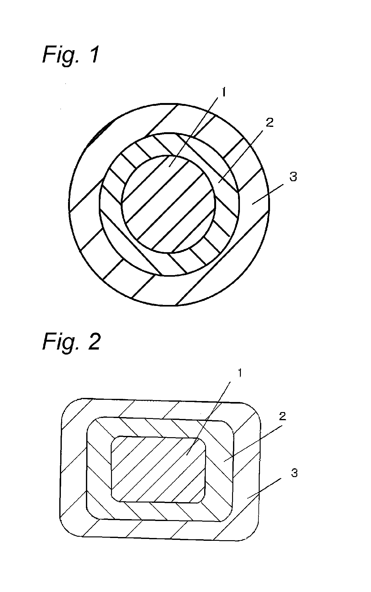
[0088]A rectangular conductor (copper of oxygen content 15 ppm) was provided, which had a dimension of 1.8 mm×3.4 mm (thickness×width) and a chamfer radius r of 0.3 mm at four corners. In forming an enamel layer, the conductor was coated with a polyamideimide resin (PAI) varnish (manufactured by Hitachi Chemical Co., Ltd., trade name: HI406, dielectric constant ∈1: 3.9), by using a die with a shape similar to the shape of the conductor, followed by passing through an 8 m-long baking furnace set to 450° C., at a speed so that the baking time period would be 15 sec, thereby to form an enamel of thickness 5 μm, via this one step of baking. This step was repeated, to form an enamel layer with thickness 25 μm, thereby to obtain an enameled wire with the coating thickness of 25 μm.

[0089]The obtained enamel wire was used as a core wire, and a screw of the extruder having 30 mm fullflight, L / D=20, and compression ratio=3 was used. As the material, polyether ether ketone (PEEK) (manufactured...

example 5

[0091]An insulated wire composed of the PEEK extrusion-coated enamel wire was obtained in the same manner as in Example 1, except that polyimide (PI) resin varnish (manufactured by UNITIKA Limited., trade name: U imide, dielectric constant ∈1: 3.5) was used instead of the polyamideimide resin varnish as the enamel resin, and the thickness of the enamel layer and the extrusion-coated layer were changed to those shown in the following Table 2. The minimum of tensile elastic modulus at a range of 25 to 250° C. and the crystallinity measured by the above-described measuring method, of the extrusion-coated resin layer, are shown in Table 2. Extrusion was carried out under the conditions of extrusion temperature shown in Table 1.

example 6

[0092]An insulated wire composed of the modified PEEK extrusion-coated enamel wire was obtained in the same manner as in Example 1, except that modified polyether ether ketone (modified-PEEK) (manufactured by Solvay Specialty Polymers, trade name: AvaSpire AV-650, dielectric constant ∈2: 3.1, melting point: 340° C.) was used instead of the polyether ether ketone as the extrusion-coated resin, and the thickness of the enamel layer and the extrusion-coated layer were changed to those shown in the following Table 2. The minimum of tensile elastic modulus at a range of 25 to 250° C. and the crystallinity measured by the above-described measuring method, of the extrusion-coated resin layer, are shown in Table 2. Extrusion was carried out under the conditions of extrusion temperature shown in Table 1.


PUM

PropertyMeasurementUnit
thicknessaaaaaaaaaa
thicknessaaaaaaaaaa
tensile elastic modulusaaaaaaaaaa

Abstract

An inverter surge-resistant insulated wire, having at least one baked enamel layer around the outer periphery of a conductor, and an extrusion-coated resin layer at the outside of the baked enamel layer, wherein a total thickness of the baked enamel layer and the extrusion-coated resin layer is 50 μm or more, a thickness of the baked enamel layer is 60 μm or less, and a thickness of the extrusion-coated resin layer is 200 μm or less, wherein the minimum of tensile elastic modulus of the extrusion-coated resin layer at a range of 25 to 250° C. is 100 MPa or more, wherein a dielectric constant of an insulation layer having a combination of the baked enamel layer and the extrusion-coated resin layer is 3.5 or less at 25° C. and 5.0 or less at 250° C., and wherein a relation between dielectric constant (∈1′) of the baked enamel layer at 250° C. and dielectric constant (∈2′) of the extrusion-coated resin layer at 250° C. satisfies (∈2′ / ∈1′)>1.

Description

CROSS-REFERENCE TO RELATED APPLICATIONS[0001]This application is a continuation of PCT / JP2013 / 079211 filed on Oct. 29, 2013 which claims benefit of Japanese Patent Application No. 2013-020887 filed on Feb. 5, 2013, the subject matters of which are incorporated herein by reference in their entirety.TECHNICAL FIELD[0002]The present invention relates to an inverter surge-resistant insulated wire.BACKGROUND ART[0003]Inverters have been employed in many types of electrical equipments, as an efficient variable-speed control unit. Inverters are switched at a frequency of several kHz to tens of kHz, to cause a surge voltage at every pulse thereof. Inverter surge is a phenomenon in which reflection occurs at a breakpoint of impedance, for example, at a starting end, a termination end, or the like of a connected wire in the propagation system, followed by applying a voltage twice as high as the inverter output voltage at the maximum. In particular, an output pulse occurred due to a high-speed...

Claims


Application Information

Patent Timeline
Patent Type & Authority Applications(United States)
IPC IPC(8): H01B3/42H01B7/02
CPCH01B3/427H01B7/0283H01B3/081H01B13/065H02K3/30Y02T10/641H01B3/307H01B3/42H01B7/02H01B7/0216H01B7/08Y02T10/64
Inventor MUTO, DAISUKEFUKUDA, HIDEOTOMIZAWA, KEIICHINAKA, SATOSHI
Owner ESSEX FURUKAWA MAGNET WIRE LLC
Why Eureka
Try Eureka