Combined decoupling and heating system

a heating system and combined technology, applied in the direction of carbon-silicon compound conductors, organic conductors, conductive materials, etc., can solve the problems of unsatisfactory reduced durability period of such coverings, and high renovation costs, so as to improve mechanical load capacity of tiling and decoupling system, improve the service life, and improve the effect of service li

Inactive Publication Date: 2015-01-22
BLANKE
View PDF18 Cites 5 Cited by
  • Summary
  • Abstract
  • Description
  • Claims
  • Application Information

AI Technical Summary

Benefits of technology

[0009]One embodiment of the invention describes a combined decoupling and heating system, in particular for laying ceramic tiling using the thin bed method, having an anchoring layer formed from a structure element for a filler compound that is to be introduced in the area of the upper side of the decoupling and heating system that is ductile during processing and hardens thereafter. Such a decoupling system of the generic kind is developed further in that the anchoring layer is formed at least in part of mechanically highly stressable reinforcement fibers made of a material that itself is electrically conducting or that has become electrically conductive through coatings and / or additives, whereby the reinforcement fibers can be heated up by conducting an electrical current thus forming the heating layer of an electrically operated area heating system. With the formation of the anchoring layer made of reinforcement fibers which are both highly mechanically stressable and heatable by conducting electrical current, the two functions of mechanical decoupling and heating can be realized in one single mechanically stable layer, which on the one hand can reduce the number of components and layers and on the other hand can significantly reduce the overall thickness of the substructure for the ceramic tiling, for example. Here, the reinforcement fibers are intended for both receiving the forces originating from the load on the ceramic tiling, for example, in the anchoring layer and transferring them decoupled to the substrate, and as a significant component of the heating layer, which is heated by conducting electrical current and can transfer this heat to, for example, the ceramic tiling and thus into the room. The fact that the fibers used for reinforcement cover essentially the entire area of the structural element and thus are essentially distributed essentially uniformly at this area is utilized in this case. Thus heating of this area is also essentially uniform without the need for integrating additional heating elements or for providing several combined layers for heating and mechanical stabilization of the heating layer as is the case with other heating systems. Furthermore, the decoupling and heating system can be installed, for example, by the floor tiler or flooring installer using methods known to him such as gluing the anchoring layer using tile adhesive or the like, and thus does not require additional crafts or persons skilled in the art for the installation. In particular, however, the overall thickness of the required layer structure for decoupling and heating is reduced significantly because, for example, separate insulating and stabilizing layers for the heating elements can be omitted since this task is assumed simultaneously by the reinforcement fibers. In addition, the different expansions between the heating elements and the other layer structure and the, for example, ceramic tiling, are reduced significantly in that the reinforcement fibers that form the heating elements enter into a close bond with the filler compound and thus can be securely connected to the ceramic tiling, for example, or other coverings as well.
[0024]It is of significant advantage for the usage properties of the decoupling and heating system according to one embodiment of the invention if the anchoring layer after introducing the filler compound is essentially filled fully with the filler compound and the reinforcement layer embedded in the fill compound fulfills a stiffening and reinforcement function for dissipating mechanical loads introduced from above. This allows for load dissipation via significantly greater layer thicknesses than with known decoupling and heating systems because the entire layer thickness of the anchoring layer additionally bears the mechanical load and at the same time is reinforced by the reinforcement layer.

Problems solved by technology

During installation of ceramic tiling using this method, problems arise whenever the substrate under the ceramic tiling is not sufficiently stable to prevent relative movement of the substrate.
This may be the case when tiling is to be laid on swaying wood floors or other insufficiently stable substrates.
The relative movability of the substrate frequently leads to a gradual destruction of the tiles, whereby the durability period of such coverings is reduced and possibly leading to high renovation costs.
However, such decoupling systems often have the disadvantage that the mechanical load capacity of the tiling and of the decoupling system is unsatisfactory.
On the one hand, anchoring of the tiles at the decoupling system was not sufficiently strong and on the other hand the compression strength of the decoupling system itself was not optimal.
However, such heating systems do also significantly stress, for example, ceramic flooring mechanically, because the different thermal expansion of the different layers of the floor heating system can cause relative movements between the ceramic flooring and its substrate, which again can lead to stress cracking and thus to a gradual destruction of the ceramic tiling.
However, this leads to a significant increase of the overall thickness of the floor structure, which is often not acceptable, for example when renovating old buildings.
Heating wires installed on top of a decoupling mat in receptacles can be used as electrical heating elements as presented in DE 10 2006 004 755 B4, however, the manual installation entails high manufacturing expenditures and also causes a respective additional layer thickness.
Furthermore, installing such separate heating layers requires additional labor expenditures and must be carried out very carefully.

Method used


Image

  • Combined decoupling and heating system
  • Combined decoupling and heating system

Examples


Embodiment Construction

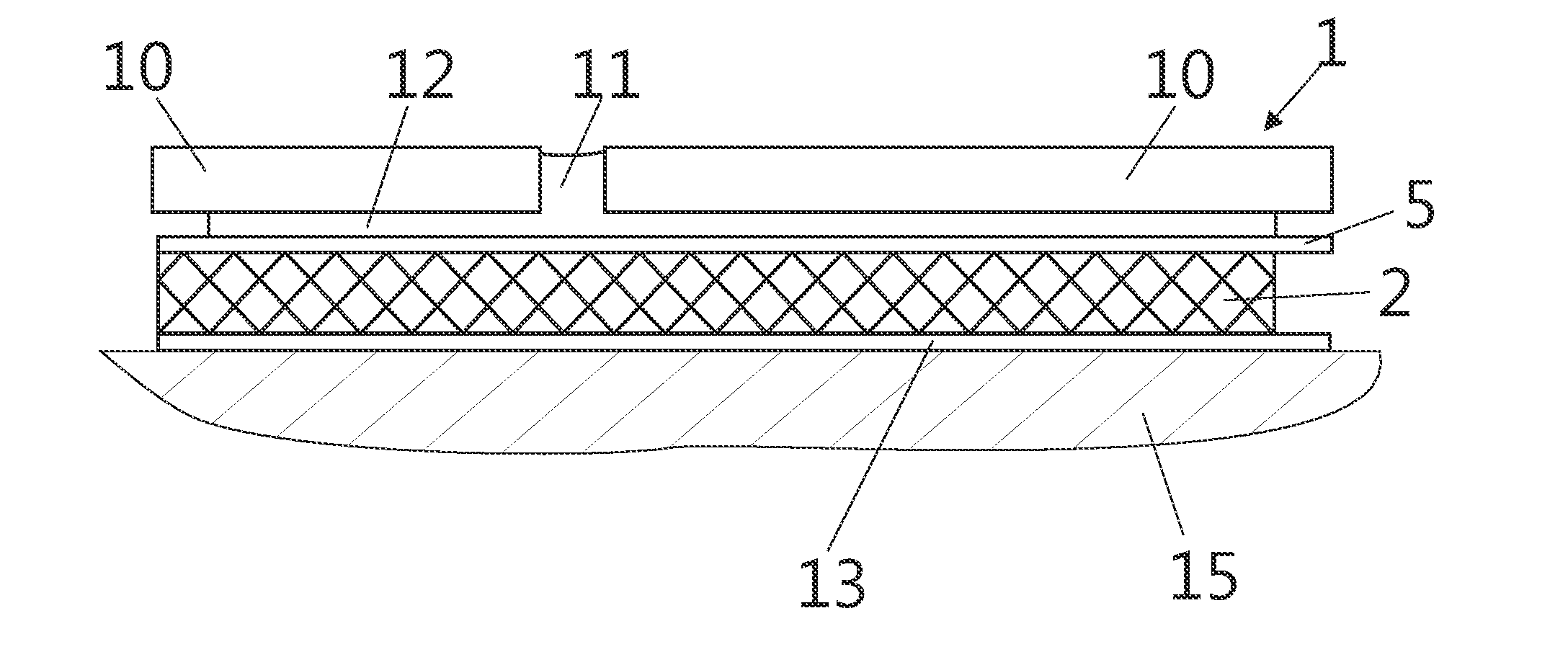
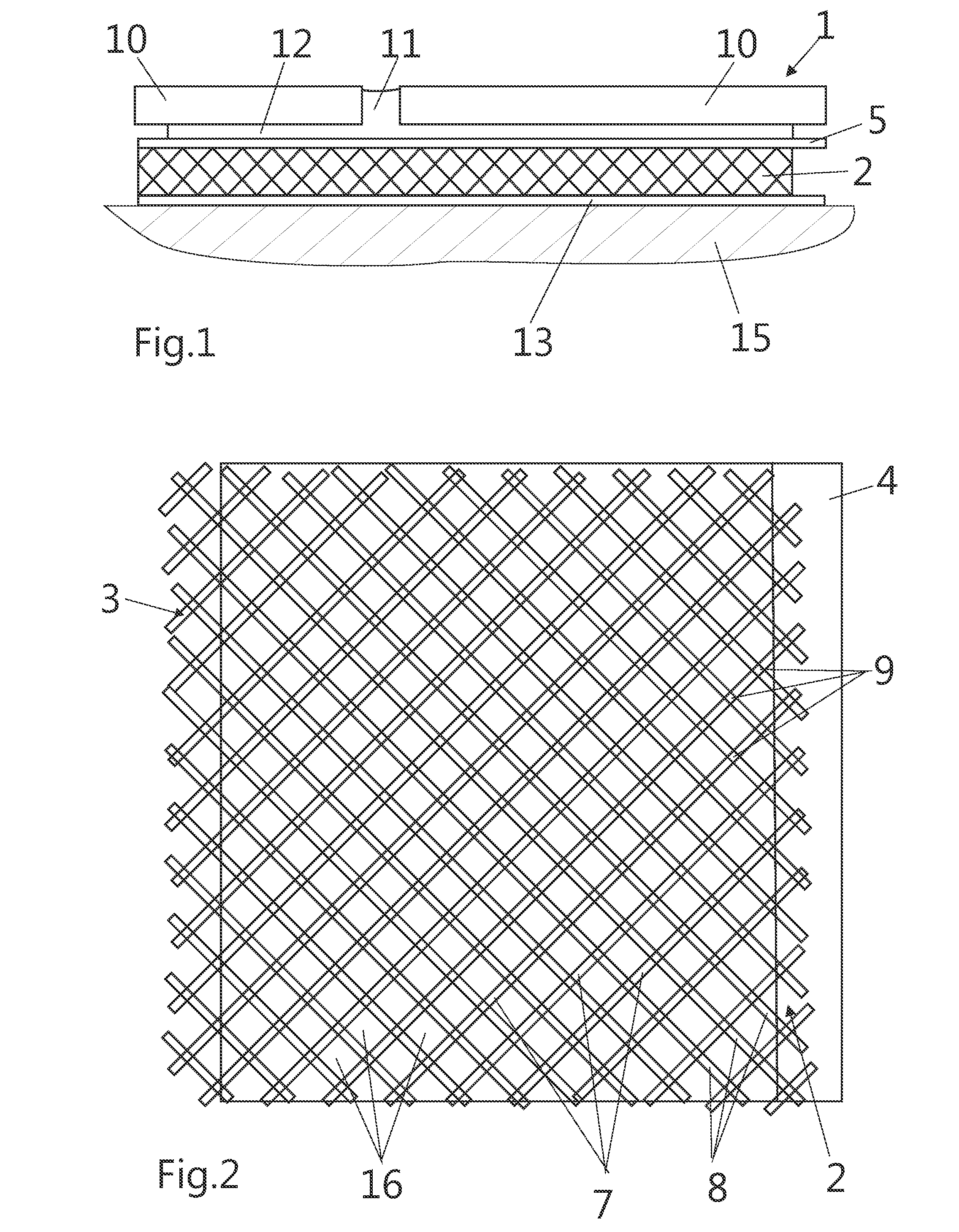
[0029]FIG. 1 shows a sectional side view of the layer structure of a combined decoupling and heating system 1 according to one embodiment of the invention, while FIG. 2 shows a top view. The decoupling and heating system 1 is shown in the installed condition on a substrate 15, for example cement screed or the like, where tiling consisting of tiles 10 that has been laid in tile mortar 12 by applying the thin bed method can be recognized above the decoupling and heating system 1 and where the joints 11 between the individual tiles 10 are also filled with tile mortar 12.

[0030]The decoupling and heating system 1 according to one embodiment of the invention has on its bottom side a nonwoven layer 13 for placement on the substrate 15. An anchoring layer 2 consisting of a lattice-like structure, which will be explained later, is connected to the nonwoven layer 13 above the nonwoven layer 13. The connection can be made, for example, by gluing or welding in a basically known manner dependent...


PUM

PropertyMeasurementUnit
thicknessaaaaaaaaaa
thicknessaaaaaaaaaa
voltagesaaaaaaaaaa

Abstract

The invention relates to a combined decoupling and heating system, in particular for installing ceramic tiling using the thin bed method, having at least one anchoring layer formed from a structure element for a filler compound that is to be introduced in the area of the upper side of the decoupling and heating system and that is ductile during processing and hardens thereafter. The anchoring layer is formed at least in part of mechanically highly stressable reinforcement fibers made of a material that itself is electrically conducting or that has become electrically conductive through coatings and / or additives, whereby the reinforcement fibers can be heated up by conducting electrical current thus forming the heating layer of an electrically operable area heating system.

Description

RELATED APPLICATIONS[0001]This application claims priority to German Patent Application No. DE 20 2013 006 416, Filed Jul. 17, 2013. This application is herein incorporated by reference in its entirety for all purposes.FIELD OF THE INVENTION[0002]The invention relates to a combined decoupling and heating system, in particular for ceramic tiling according to the thin bed methodBACKGROUND OF THE INVENTION[0003]Today, ceramic tiling and in particular tiles are usually installed according to the so-called thin bed method, where the ceramic tiling is laid in a thin tile mortar adhesion layer. During installation of ceramic tiling using this method, problems arise whenever the substrate under the ceramic tiling is not sufficiently stable to prevent relative movement of the substrate. This may be the case when tiling is to be laid on swaying wood floors or other insufficiently stable substrates. The relative movability of the substrate frequently leads to a gradual destruction of the tiles...

Claims


Application Information

Patent Timeline
Patent Type & Authority Applications(United States)
IPC IPC(8): H05B3/03
CPCH05B3/03E04F15/182E04F15/186F24D13/024H05B3/12H05B3/145H05B3/146H05B3/34H05B3/342H05B2203/011H05B2203/014H05B2203/026Y02B30/26Y02B30/00
Inventor BLANKE, PETER
Owner BLANKE
Why Eureka
Try Eureka