PLGA scaffold
a cell scaffold and polymer technology, applied in the field of polymer polymer polymer coglycolide, can solve the problems of difficult application of cell scaffolds, and achieve the effects of improving cell adhesion and cell growth, and excellent biocompatibility
- Summary
- Abstract
- Description
- Claims
- Application Information
AI Technical Summary
Benefits of technology
Problems solved by technology
Method used
Image
Examples
example 1
Preparation of Elastin-Like Artificial Extracellular Matrix
[0087]The TGPG[VGRGD(VGVPG)6]20WPC (REP) matrix was used as an elastin-like artificial extracellular matrix. The REP matrix was obtained using the plasmid pET-25b(+)-1 (Novagen, U.S.A.). After being expressed, the REP matrix was isolated from E. coli BLR(DE3) by inverse thermal cycling. Then, the REP matrix was dissolved in PBS (phosphate buffered saline; pH 7.4, Gibco, U.S.A.).
example 2
[0088]A cell scaffold was fabricated on the basis of PLGA (poly(D,L-lactide-co-glycolide), lactide:glycolide=50:50, Mw 40,000-75,000, Sigma-Aldrich, U.S.A.). In this context, the PLGA scaffold was prepared by a gas foaming method using NaHCO3 (Duksan Chemicals, Korea) as an inducer. In a falcon tube, 1 g of PLGA was dissolved in 30 ml of CHCl3 with the aid of a shaking rotator. This PLGA solution was aliquoted to 10 vials (width 1.5 cm×height 6.5 cm), each containing 2 g of NaHCO3 (diameter 53˜106 μm), with the mass ratio of NaHCO3:PLGA set forth as 15:1. Afterwards, the PLGA solution was dried for 2 days under a laminar flow hood and then, for 12 hrs at 25° C. in a vacuum to give a PLGA scaffold. This PLGA scaffold was rendered porous by treatment with 5 ml of citric acid in the vial for 2 days on a shaking rotator. After removal of the citric acid from the vial by aspiration, the PLGA scaffold was washed twice with 5 ml of PBS, and dried at 25° C. for 1...
example 3
Surface Modification of PLGA Scaffold
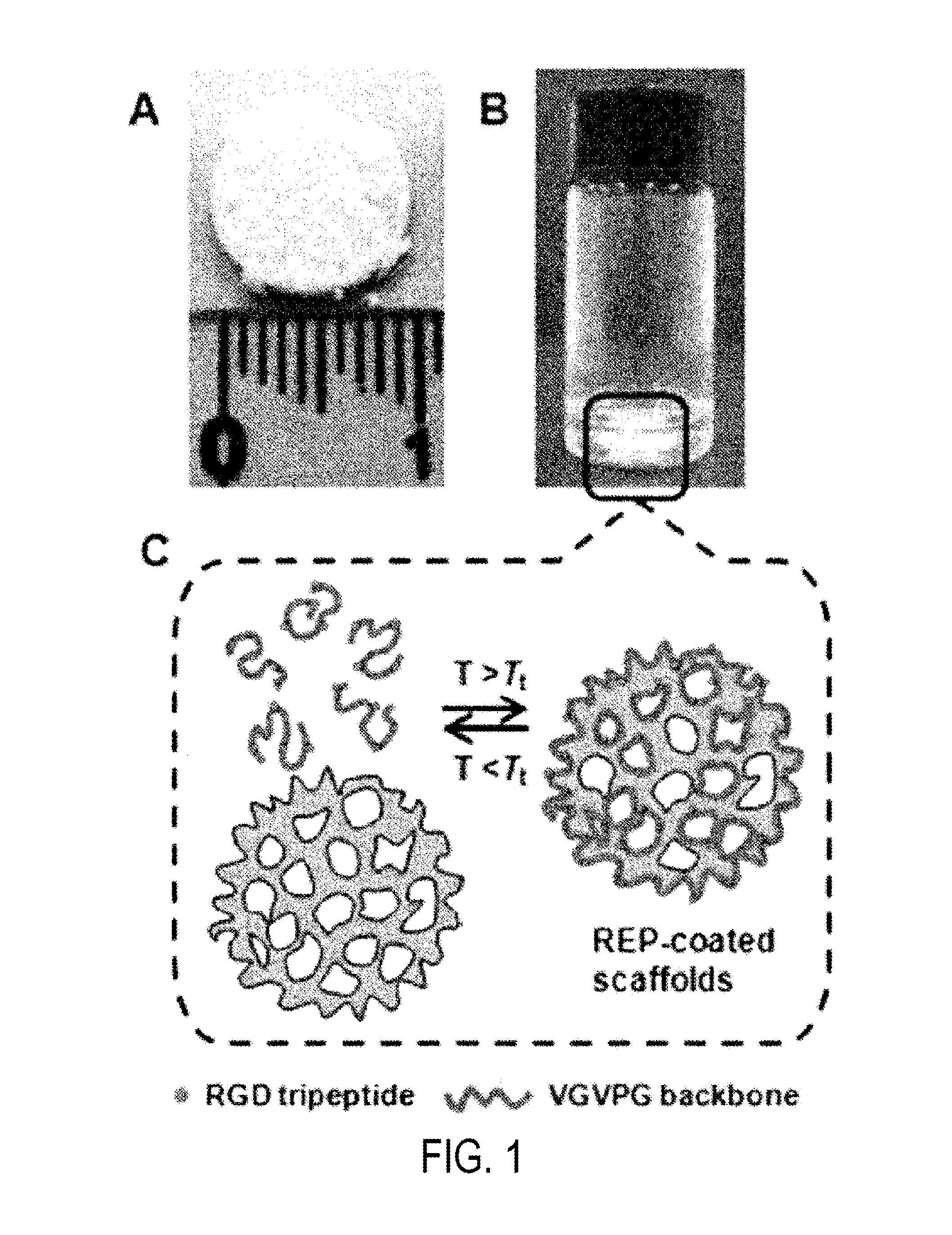
[0089]The PLGA scaffold prepared in Example 2 was immersed, together with 30 μg, 60 μg, 300 μg, 600 μg or 1200 μg of the REP matrix prepared in Example 1, in 1 ml of PBS in a vial (diameter 2 cm×5 cm) and left for 2 hrs at 4° C. Then, the PLGA scaffold was incubated at 37° C. for 1 hr in a cell culture chamber to allow for surface modification thereon. The procedure of coating the PLGA scaffold with the REP matrix is illustrated in FIG. 1.
[0090]FIG. 1A is a macroscopic appearance of the PLGA scaffold while FIG. 1B shows the PLGA scaffold immersed in the REP matrix. FIG. 1C schematically illustrates the process of modifying the surface of the PLGA scaffold with the REP matrix through thermal transformation.
[0091]Hereinafter, the PLGA scaffold was designated S1 when coated with 30 μg of the REP matrix, S2 when coated with 60 μg of the REP matrix, S3 when coated with 300 g of the REP matrix, S4 when coated with 600 μg of the REP matrix, and S5 when ...
PUM
| Property | Measurement | Unit |
|---|---|---|
| porosity | aaaaa | aaaaa |
| structure | aaaaa | aaaaa |
| cross sectional area | aaaaa | aaaaa |
Abstract
Description
Claims
Application Information
 - R&D
- Intellectual Property
- Life Sciences
- Materials
- Tech Scout
- Unparalleled Data Quality
- Higher Quality Content
- 60% Fewer Hallucinations
Browse by: Latest US Patents, China's latest patents, Technical Efficacy Thesaurus, Application Domain, Technology Topic, Popular Technical Reports.
© 2025 PatSnap. All rights reserved.Legal|Privacy policy|Modern Slavery Act Transparency Statement|Sitemap|About US| Contact US: help@patsnap.com


