Novel flow battery and usage thereof

a flow battery and flow technology, applied in the field of flow batteries, can solve the problems of limited cycle life, poor energy efficiency, limited energy of hybrid flow batteries, etc., and achieve the effect of preventing free access to ferricyanide and facilitating the redox process of conversion

Inactive Publication Date: 2015-02-19
EPSILOR ELECTRIC FUEL
View PDF8 Cites 18 Cited by
  • Summary
  • Abstract
  • Description
  • Claims
  • Application Information

AI Technical Summary

Benefits of technology

[0015]The cathode may be a catalytic porous structure, comprising nickel or carbon, that facilitates the redox process of conversion from ferrocyanide to ferricyanide on charge and the reverse reaction on discharge. Furthermore, a separator, such as an ion selective membrane may be placed between the anode and cathode to prevent free access of ferricyanide to the iron anode—which would cause self discharge.

Problems solved by technology

However, as with typical batteries, the energy of the hybrid flow battery is limited by the size of the battery electrodes.
Hybrid flow battery systems still require two pumps and two tanks and often have limited cycle life or poor energy efficiency due to metal dendrite formation and excessive parasitic hydrogen evolution on charging.

Method used


Image

  • Novel flow battery and usage thereof
  • Novel flow battery and usage thereof
  • Novel flow battery and usage thereof

Examples


Embodiment Construction

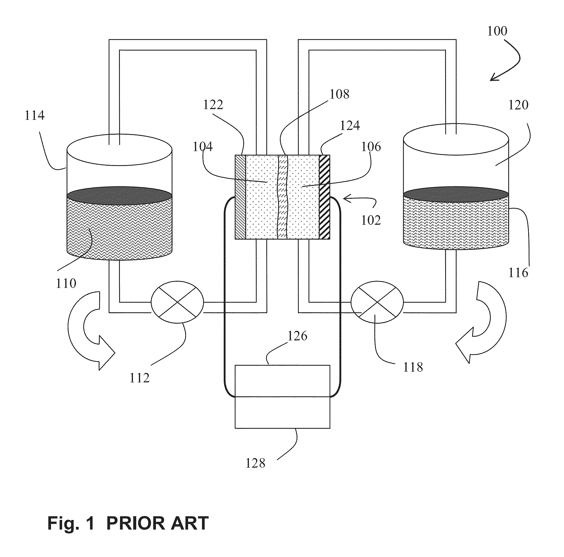
[0043]With reference to FIG. 1, a flow cell 100 of the prior art is shown. Flow cell 100 consists of a voltaic battery cell 102 having two half cells 104, 106 separated by an ion selective membrane 108. A first half cell 104 contains a first electrolyte solution 110 that is pumped via a pump 112 from a reservoir, or first electrolyte tank 114. A second half cell 106 contains a second electrolyte solution 116 that is pumped via a pump 118 from a second electrolyte tank 120. An anode 122 is in electrical contact to the first half cell 104, and a cathode 124 is in electrical contact with the second half cell 106. On discharge, the first electrolyte 110 is pumped from first electrolyte tank 114 by pump 112 to the first half cell 104 where electrons are stripped from, for example, metal ions (cations) of the electrolyte 110 and the valency of the cations increases. In the second half cell 106, electrons are added to, for example, metal ions, and their valency decreases. There is a net vo...


PUM

PropertyMeasurementUnit
voltagesaaaaaaaaaa
structureaaaaaaaaaa
flexibleaaaaaaaaaa

Abstract

A voltaic cell comprising an iron in alkali anode where metal iron is oxidized to iron II hydroxide and a ferricyanide in alkali cathode where ferricyanide is reduced to ferrocyanide, and uses thereof.

Description

PRIORITY INFORMATION[0001]The present application claims priority to Israeli Patent Application No: 227961 filed Aug. 14, 2013.BACKGROUND[0002]1. Field of the Disclosure[0003]The present invention relates to fuel cells and batteries and in particular to flow batteries for the rechargeable generation of electricity.[0004]2. Description of the Related Art[0005]Flow batteries are rechargeable fuel cells in which electrolyte containing one or more dissolved electro-active species flows through an electrochemical cell that reversibly converts chemical energy directly to electricity. Additional electrolyte is stored externally, generally in one or more storage tanks, and is usually pumped through the cell (or cells) of the reactor, although gravity feed systems are also known. Flow batteries can be rapidly “recharged” by replacing the electrolyte liquid; the spent material being simultaneously recovered and reenergized.[0006]Various classes of flow batteries exist. One type of flow batter...

Claims


Application Information

Patent Timeline
Patent Type & Authority Applications(United States)
IPC IPC(8): H01M8/18H01M8/04H02J7/35H01M8/20H02J7/00H01M4/58H01M10/46H01M4/52
CPCH01M8/188H01M4/5825H01M8/04201H02J7/355H01M10/46H01M8/20H02J7/0042H01M10/465H01M8/04186H01M8/04208H01M2250/10H01M2250/20Y02B90/10Y02E60/50Y02T90/40Y02E60/10H02J7/35
Inventor GOLDSTEIN, JONATHAN R.
Owner EPSILOR ELECTRIC FUEL
Why Eureka
Try Eureka