Lithography apparatus and method for producing a mirror arrangement

Active Publication Date: 2015-02-26
CARL ZEISS SMT GMBH
View PDF2 Cites 12 Cited by
  • Summary
  • Abstract
  • Description
  • Claims
  • Application Information

AI Technical Summary

Benefits of technology

[0027]In accordance with this production method, the mounting elements are initially attached to the cover elements, and only then is the shape of the cover element adapted to the shape of the annular side wall to which the cover element is attached. Deformations possibly occurring during the

Problems solved by technology

Furthermore, there is no material which is sufficiently transparent in the aforementioned wavelength range, which is why mirrors are used as optical elements for shaping and guiding the EUV radiation.
Mirrors with large diameters are, on the one hand, costly in production and, on the other hand, make low-deformation mounting and actuation more difficult.
A disadvantage in the arrangement shown in FIG. 1 is that th

Method used


Image

  • Lithography apparatus and method for producing a mirror arrangement
  • Lithography apparatus and method for producing a mirror arrangement
  • Lithography apparatus and method for producing a mirror arrangement

Examples


Example

[0045]If nothing else is specified, the same reference signs in the figures denote the same or functionally equivalent elements. Furthermore, it should be noted that the illustrations in the figures are not necessarily drawn to scale.

BEST MODE FOR CARRYING OUT THE INVENTION

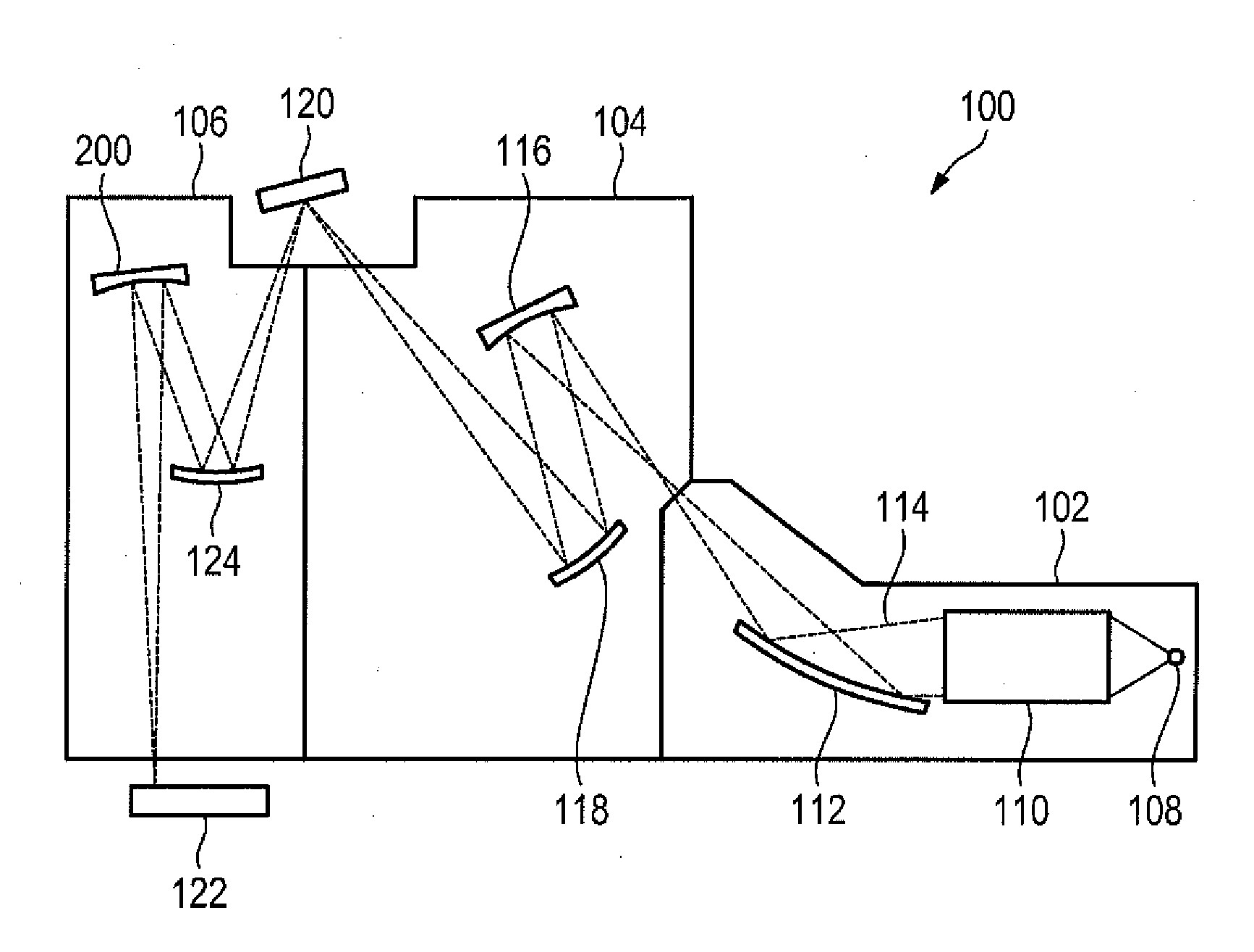
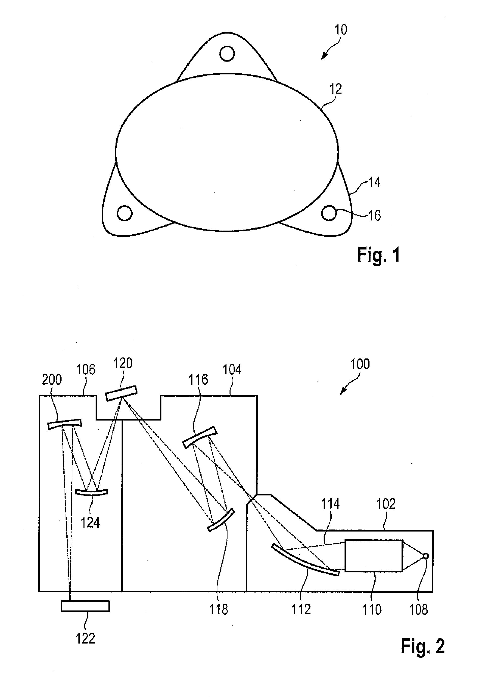
[0046]FIG. 2 shows a schematic view of an EUV lithography apparatus 100 in accordance with one embodiment, which comprises a beam shaping system 102, an illumination system 104 and a projection system 106. The beam shaping system 102, the illumination system 104 and the projection system 106 are respectively provided in a vacuum housing, which is evacuated with the aid of an evacuation device (not illustrated in any more detail). The vacuum housing is surrounded by a machine room (not illustrated in any more detail), in which the drive devices for mechanical displacement or adjustment of the optical elements are provided. Furthermore, electric controls and the like can also be provided in this machine room.

[0047]T...


PUM


Abstract

A lithography apparatus is disclosed, having at least one mirror arrangement which includes a mirror substrate including a front side with a reflecting surface, a side wall, which extends along a circumference of the mirror substrate from a rear side of the mirror substrate, and mounting elements to mount the mirror arrangement on a structural element of the lithography apparatus. The rear side of the mirror substrate and an inner side of the side wall delimit a cavity. Each of the mounting elements is connected to the mirror arrangement at a connection surface. The relation S/D>0.5 is satisfied at least one of the connection surfaces, wherein D denotes a thickness of the side wall at the connection surface and S denotes the length of the shortest path through the mirror material from the centroid of the connection surface to the rear side of the mirror substrate.

Description

CROSS-REFERENCE TO RELATED APPLICATIONS[0001]The present application is a continuation of, and claims benefit under 35 USC 120 to, international application PCT / EP2013 / 061096, filed May 29, 2013, which claims benefit under 35 USC 119 of the German patent application DE 10 2012 209 309.5, filed Jun. 1, 2012 and U.S. patent application 61 / 654,179, filed Jun. 1, 2012. The whole description of each of these applications is incorporated herein by reference.FIELD OF THE INVENTION[0002]The invention relates to a lithography apparatus with one or more mirror arrangements, and a method for producing a mirror arrangement for such a lithography apparatus.RELATED ART[0003]By way of example, lithography apparatuses are used in the production of integrated circuits (ICs) in order to image a mask pattern in a mask onto a substrate such as e.g. a silicon wafer. Here, a light beam generated by an illumination device is directed onto the substrate through the mask. An exposure lens, which consists of...

Claims


Application Information

Patent Timeline
IPC IPC(8): G03F7/20G02B7/182G02B5/08
CPCG03F7/702G02B7/182G02B5/0891G03F7/70825
Inventor SCHAFFER, DIRKCLAUSS, WILFRIEDCHUNG, HIN-YIU ANTHONY
Owner CARL ZEISS SMT GMBH
Why Eureka
Try Eureka