High Frequency Integrated Point-of-Load Power Converter with Embedded Inductor Substrate

a point-of-load power converter and inductor substrate technology, applied in the direction of inductance, electrical apparatus contruction details, association of printed circuit non-printed electric components, etc., can solve the problems of memory chips generally requiring little power during normal operation, high cost, and high cos

Active Publication Date: 2015-03-05
VIRGINIA TECH INTPROP INC
View PDF2 Cites 31 Cited by
  • Summary
  • Abstract
  • Description
  • Claims
  • Application Information

AI Technical Summary

Benefits of technology

[0014]These three aspects of the invention can be used in any combination and, when all of these aspects of the invention are used together, provide a power converter structure having a power density closely approaching 2 KW / in3 when operating at switching frequencies of 1.5-2 MHZ which is easily achieved with commercially available and mature technologies suitable for mass production.

Problems solved by technology

However, in many such devices, current can fluctuate very rapidly.
Similarly, memory chips generally require little power during normal operation but may require substantial power for periodic refresh which must be performed rapidly and often.
Therefore, it is considered imperative to develop and use power converters for such devices that are as small and light weight as possible since the power converter(s) do not directly contribute to the ultimate functionality of the device.
While much effort has been expended in recent years to provide power converters of reduced size and increased power density, none has satisfied all power converter requirements for hand-held devices of current and foreseeable designs.
Very high frequency switching devices based on gallium nitride (GaN) combined with low temperature co-fired ceramic (LTCC) ferrite inductor substrates have reached power densities of 1 Kw / in3 but are too expensive, the technology of GaN devices is not sufficiently mature and the high temperatures (˜900° C.) required for sintering ferrite materials complicates manufacturing and raises costs too greatly for high volume manufacture.

Method used


Image

  • High Frequency Integrated Point-of-Load Power Converter with Embedded Inductor Substrate
  • High Frequency Integrated Point-of-Load Power Converter with Embedded Inductor Substrate
  • High Frequency Integrated Point-of-Load Power Converter with Embedded Inductor Substrate

Examples


Embodiment Construction

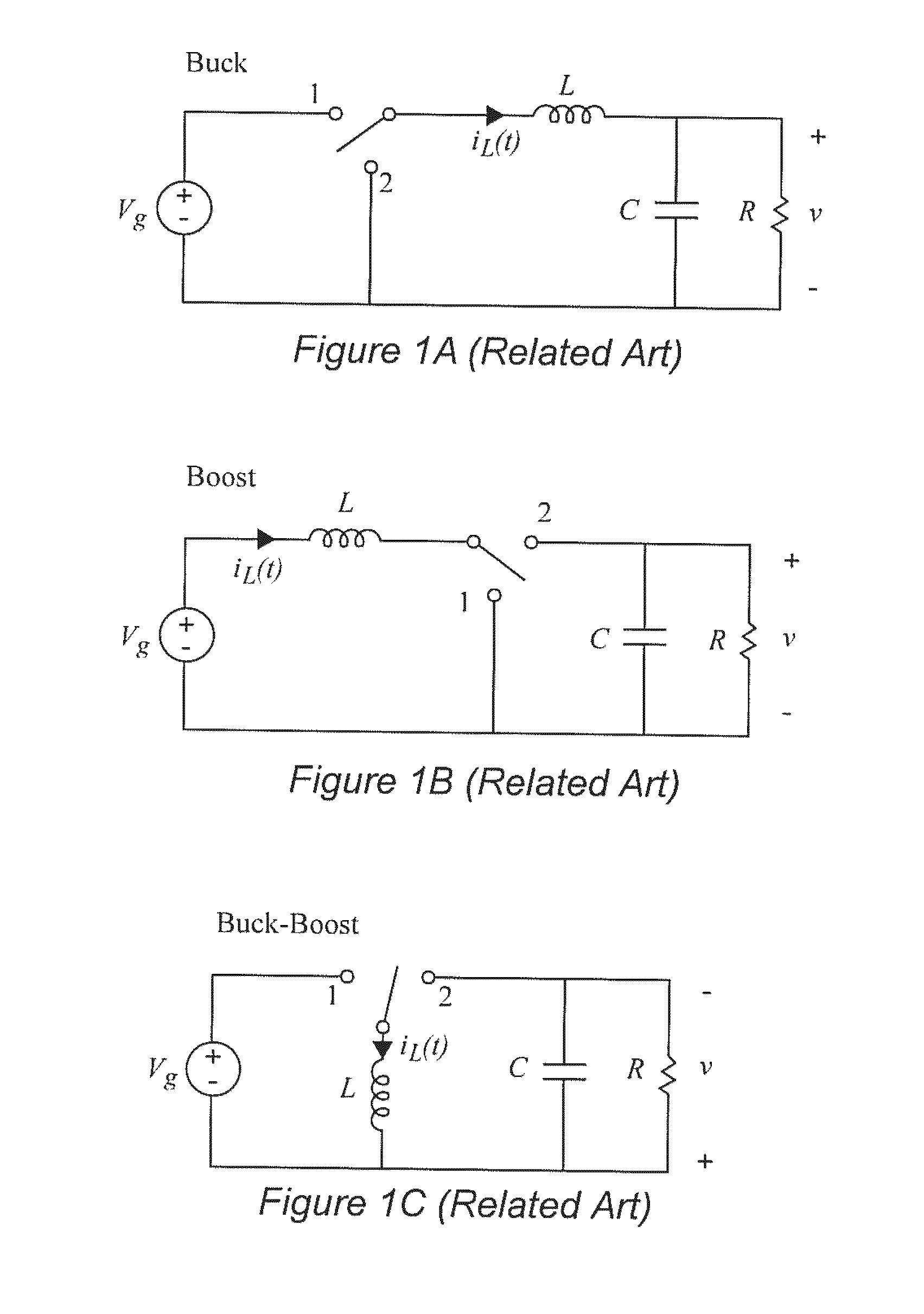
[0027]Referring now to the drawings, and more particularly to FIGS. 1A-1C, there are shown schematic diagrams of three exemplary basic types of power converter topologies that can be implemented in accordance with the invention. While the modes of operation of these topologies are well-known, many variants of the actual circuits have been developed to which the invention is also applicable. The invention is also applicable to any other power converter topology as long as the magnetic components are included, whether currently known or foreseeable.

[0028]It should be understood that the schematic diagrams of FIGS. 1A-1C are simplified to the minimum required components for each topology and are arranged to facilitate conveyance of an understanding of the invention and the problems for which the invention provides a solution. Therefore, no portion of any of FIGS. 1A-1C is admitted to be prior art as to the present invention. Therefore these Figures have been labeled as “Related Art”.

[0...


PUM


Abstract

A low profile power converter structure is provide wherein volume is reduced and power density is increased to approach 1 KW/in3 by at least one of forming an inductor as a body of magnetic material embedded in a substrate formed by a plurality of printed circuit board (PCB) lamina and forming inductor windings of PCB cladding and vias which may be of any desired number of turns and may include inversely coupled windings and which provide a lateral flux path, forming the body of magnetic material from high aspect ratio flakes of magnetic material which are aligned with the inductor magnetic field in an insulating organic binder and hot-pressed and providing a four-layer architecture comprising two layers of PCB lamina including the embedded body of magnetic material, a shield layer and an additional layer of PCB lamina, including cladding for supporting and connecting a switching circuit, a capacitor and the inductor.

Description

CROSS-REFERENCE TO RELATED APPLICATIONS[0001]This application claims benefit of priority of U.S. Provisional Application 61 / 872,212, filed Aug. 30, 2013, which is hereby incorporated by reference in its entirety.FIELD OF THE INVENTION[0002]The present invention generally relates to point-of-load (POL) power converters and, more particularly, POL power converters having very high power density as is particularly desirable for portable electronic devices.BACKGROUND OF THE INVENTION[0003]Virtually all electronic devices operate on power which must be of substantially constant, if not very closely regulated voltage and thus require a power supply capable of delivering power at such voltage(s), often at relatively high current. However, in many such devices, current can fluctuate very rapidly. The voltages required can also differ widely between such devices and within a given device. For example, modern microprocessor chips, when operating at full clock speeds may require hundreds of am...

Claims


Application Information

Patent Timeline
Patent Type & Authority Applications(United States)
IPC IPC(8): H05K7/02
CPCH05K7/02H01F17/0033H01F2017/008H02M3/155H05K1/0233H05K1/0373H05K1/165H05K2201/0209H05K2201/0245H05K2201/086H05K2201/10015
Inventor SU, YIPENGLI, QIANGLEE, FRED C.ZHANG, WENLI
Owner VIRGINIA TECH INTPROP INC
Why Eureka
Try Eureka