Management of Gas Pressure and Electrode State of Charge in Alkaline Batteries

Active Publication Date: 2015-03-05
RES FOUND THE CITY UNIV OF NEW YORK
3 Cites 7 Cited by

AI-Extracted Technical Summary

Problems solved by technology

Unfortunately, the electrochemical reactions that generate the gases compete with electrochemical reactions for storing energy.
Thus gas generation reduces the efficiency of the battery for storing energy.
In addition, if more Coulombs go toward oxygen (hydrogen) gas generation than toward hydrogen (oxygen) gas generation the cathode (anode) has a lower state of charge (SOC) than the anode (cathode), which can lead to overall poor performance and to battery short-circuiting.
Both in...

Abstract

An inventive, new system that measures gas composition and pressure in the headspace of an aqueous electrolyte battery is described. The system includes a microcontroller that can use the composition and pressure information to connect a third electrode to either the anode(s) or the cathode(s) in order to balance the state of charge between the two. Results have shown that such a system can control the gas pressure inside a sealed flooded aqueous electrolyte battery to remain below 20 kPa (3 psi) and greatly extend the useable life of the battery.

Application Domain

Batteries circuit arrangementsFinal product manufacture +9

Technology Topic

State of chargeGas composition +10

Image

  • Management of Gas Pressure and Electrode State of Charge in Alkaline Batteries
  • Management of Gas Pressure and Electrode State of Charge in Alkaline Batteries
  • Management of Gas Pressure and Electrode State of Charge in Alkaline Batteries

Examples

  • Experimental program(1)

Example

EXAMPLE
[0039]The following example provides details relating to composition, fabrication and performance characteristics of an electrochemical cell in accordance with some embodiments of the present invention. It should be understood the following is representative only, and that the invention is not limited by the detail set forth in this example.
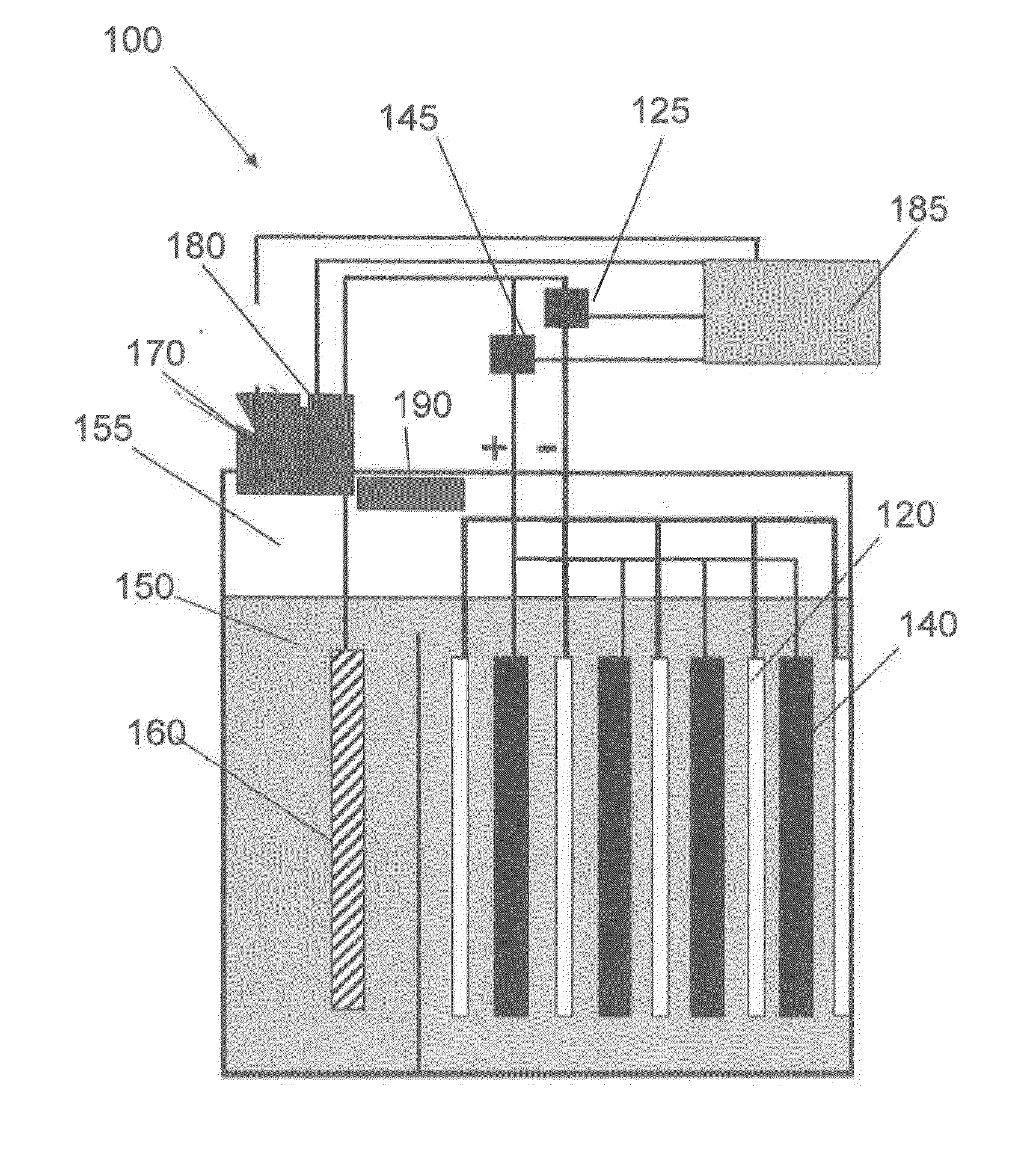
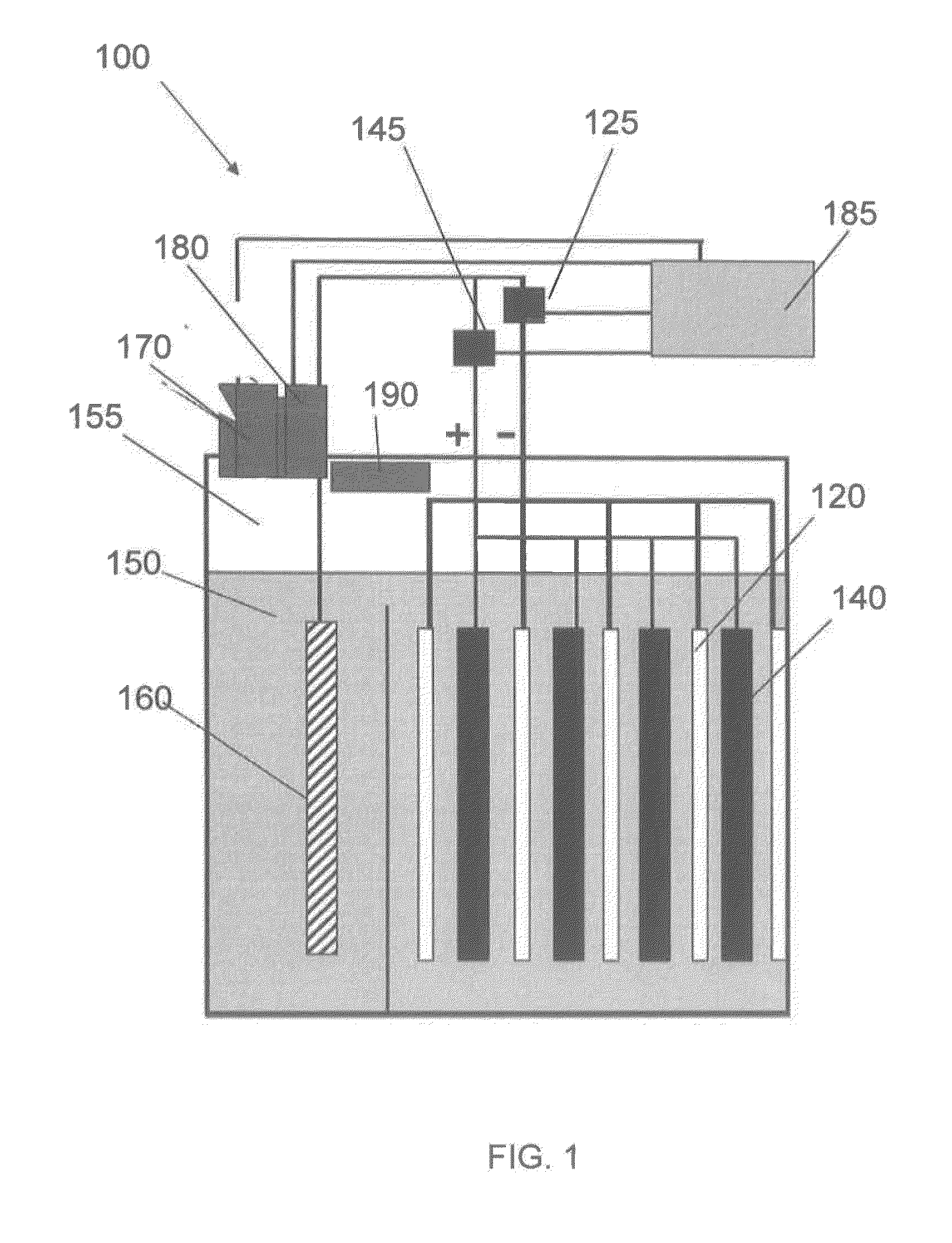
[0040]A 34-Wh prototype battery cell was made from 8 NiOOH cathodes and 9 nickel-sheet anodes, all measuring about 10 cm×9 cm. An aqueous solution of 37% w/w potassium hydroxide and 60 g/L ZnO was used as the electrolyte. The cathodes were separated from the anodes by a 3 mm gap, and a pump forced flow of 0.5 cm/s through the channel formed by the gap. No membrane or separator was used. The sealed cell case was about 17 cm tall×6 cm wide×14 cm long. The third electrode was a single nickel foam sheet of the same size as the other electrodes. The cell was cycled at 95% of its total storage capacity during measurement of the data shown in the graph in FIG. 2 and achieved Coulombic efficiencies above 90% and energy efficiencies above 80%. A high-surface-area platinum recombiner was placed in the headspace of the cell.
[0041]FIG. 4 shows a plot of pressure as a function of time for the prototype battery cell. The prototype operated for more than 35 consecutive charge/discharge cycles with gas partial pressures remaining under about 20 kPa (3 psi).
[0042]The data in FIG. 4 show that a novel advance has been made for sealed flooded battery cell technology. Typically, pressure inside a sealed, flooded aqueous nickel hydroxide-zinc battery rises above the safety limit of about 35 kPa (5 psi) after two or three cycles and continues to rise to extreme pressures of about 70 to 700 kPa (10 to 100 psi) within ten cycles. Similar increases in pressure occur in a sealed flooded lead-acid battery. Because of this, the lead-acid industry has not been able to commercialize sealed, flooded lead-acid batteries. The data presented in FIG. 2 shows that the novel, new technology described herein allows operation of flooded aqueous batteries for an indefinite number of cycles by keeping gauge gas pressure below 20 kPa (3 psi) without having to vent gases to the environment.
[0043]This invention has been described herein in considerable detail to provide those skilled in the art with information relevant to apply the novel principles and to construct and use such specialized components as are required. However, it is to be understood that the invention can be carried out by different equipment, materials and devices, and that various modifications, both as to the equipment and operating procedures, can be accomplished without departing from the scope of the invention itself

PUM

no PUM

Description & Claims & Application Information

We can also present the details of the Description, Claims and Application information to help users get a comprehensive understanding of the technical details of the patent, such as background art, summary of invention, brief description of drawings, description of embodiments, and other original content. On the other hand, users can also determine the specific scope of protection of the technology through the list of claims; as well as understand the changes in the life cycle of the technology with the presentation of the patent timeline. Login to view more.
Why Eureka
Try Eureka