Apparatus and method for processing biomass

a biomass and apparatus technology, applied in the field of apparatus and methods for processing biomass, can solve the problems of high cost, high carbon dioxide return to the atmosphere, and complex carbon dioxide storage, and achieve the effect of more plasma power

Active Publication Date: 2015-03-12
CARBONSCAPE
View PDF7 Cites 21 Cited by
  • Summary
  • Abstract
  • Description
  • Claims
  • Application Information

AI Technical Summary

Benefits of technology

[0149]In an alternative embodiment, the biomass is so that the biomass does not absorb electromagnetic energy not absorbed by the microwave absorbing material. The biomass may be contained in a second reaction container and not exposed to the electromagnetic energy. In this alternative embodiment, pyrolys

Problems solved by technology

Sequestration of carbon in gaseous form (as the gas is released, for example at power plants) is a technically complex and high cost solution.
In addition, the carbon dioxide that is stored in trees can only be held if the area remains forested If the area is cleared, much of the carbon dioxide returns to the atmosphere.
Biomass has a poor thermal conductivity and as the mass reaches approximately 300° C. it begins to degrade endothermically.
Some of the products of such thermal degradation are highly

Method used


Image

  • Apparatus and method for processing biomass
  • Apparatus and method for processing biomass
  • Apparatus and method for processing biomass

Examples


example 1

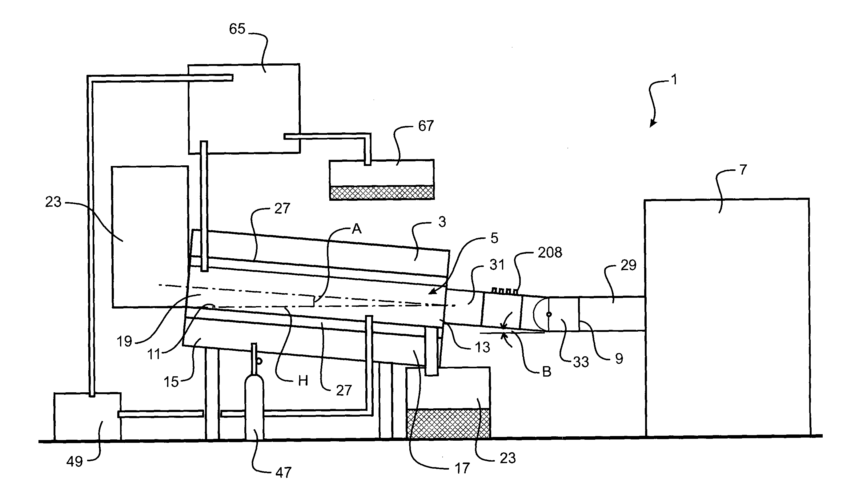
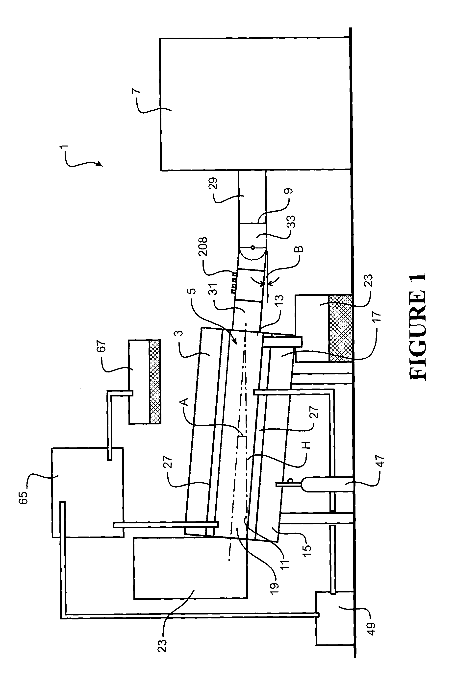
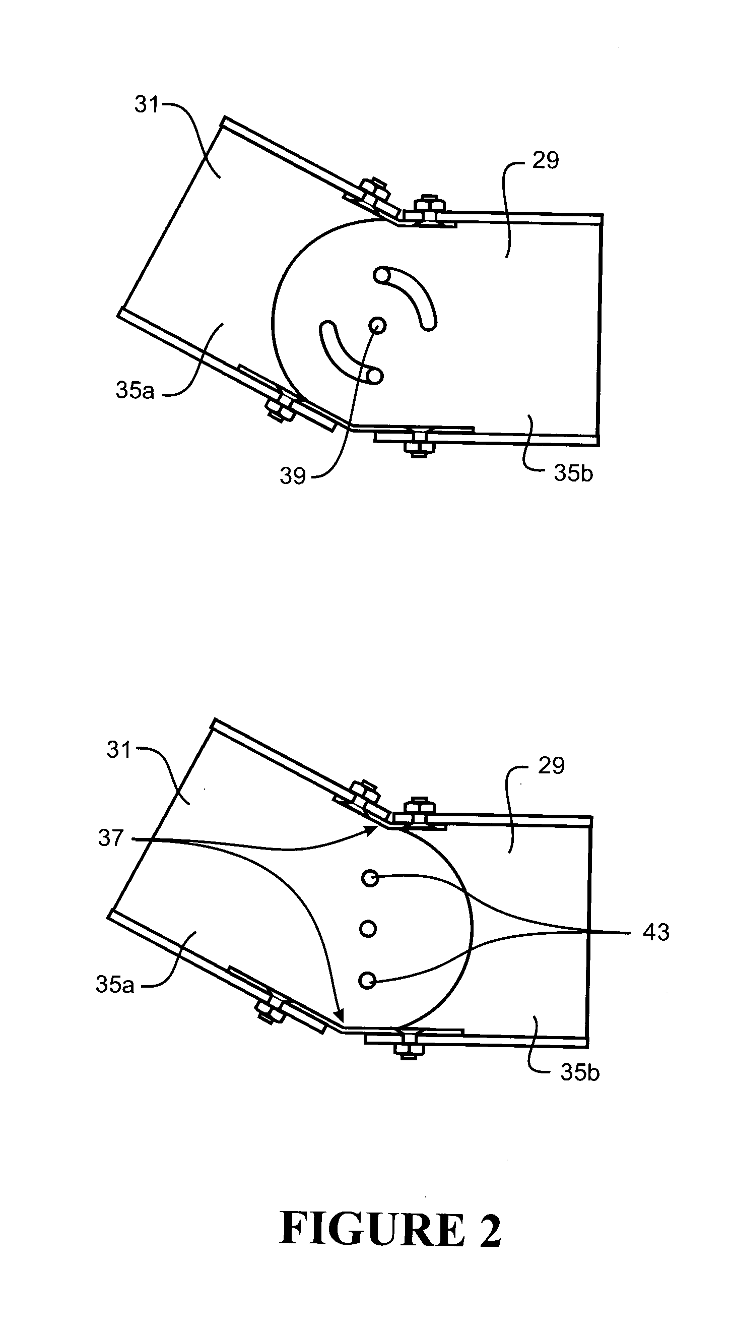
[0375]Sawdust (50 g) was placed in a clean quartz reaction container, and carbon dioxide was passed over it at a rate of 40 L / min. The absorbed microwave energy was initially 3 kW.

[0376]After about 6 minutes, during which time the temperature of the sawdust was 305° C., what we believe to be a plasma formed, together with a deep orange heat glow that commenced on the inside of the quartz, which was sustained for a brief period following the power being turned off. During this period, power absorption was 7.6 kW and the temperature reached 871° C. At the end of 20 minutes, 6 g of charcoal was obtained, which had a surface area of 705 m2 / gram.

example 2

[0377]Sawdust (50 g) impregnated with 35 g of heavy pyrolysis tar was placed in a quartz reaction container, the inner surface of which was coated with carbon from previous runs, and carbon dioxide was passed over it at a rate of 40 L / min. The absorption of microwave energy was initially 5 kW, which subsequently rose to 7 kW following intermittent plasma formation and the orange surface glow. The temperature reached 756° C. At the end of 20 minutes, 12 g of charcoal was obtained, which had a surface area of 446 m2 / gram.

example 3

[0378]Sawdust (50 g) was placed in a quartz reaction container, the inner surface of which was coated with carbon from previous runs, and carbon dioxide was passed over it at a rate of 40 L / min. The orange glow appeared after about 1 minute, and microwave power was absorbed at 5 kW initially, and after 9 min, 6.5 kW. The applied power was then reduced to maintain 5 kW. At the end of 23 minutes, power ceased and 4 g of charcoal was obtained, which had a surface area of 637 m2 / gram.


PUM

PropertyMeasurementUnit
Temperatureaaaaaaaaaa
Pressureaaaaaaaaaa

Abstract

There is provided an apparatus (1) and methods for processing biomass to produce charcoal, bio-oil(s) activated carbon, recarburiser carbon, or nut coke by means of microwave energy. The apparatus has a rotatable tube (5) for receiving biomass (108), an electromagnetic generator (7). One method provides applying electromagnetic energy to the biomass (108) and an absorbing material (109). An alternative method provides allowing an indirect, black body radiation field to develop, and exposing the biomass (108) to the black body radiation field and the electromagnetic energy. Another method provides allowing plasma to form and exposing the biomass to the plasma and the electromagnetic energy. Another method provides introducing the biomass to a second container (205), introducing the second container to a first reaction container (5), applying electromagnetic energy to the biomass and an absorbing material (109), allowing a plasma to form in the first container, which heats the biomass in the second container.

Description

CROSS REFERENCE TO RELATED APPLICATIONS[0001]This application is the National Stage of International Application No. PCT / NZ2012 / 000213, filed on Nov. 21, 2012, which claims the benefit of New Zealand Application No. 596549 filed on Nov. 21, 2011. The contents of both applications are hereby incorporated by reference in their entirety.FIELD OF THE INVENTION[0002]The present invention relates to an apparatus and method for processing biomass. In particular, the present invention relates to an apparatus and method for making charcoal, bio-oil(s) activated carbon, recarburiser carbon, or nut coke from biomass by means of microwave energy.BACKGROUND[0003]There is considerable concern over the current volume of greenhouse gas emissions and the effect that these may have on the global climate. Carbon dioxide (CO2) is the principal greenhouse gas believed to be driving anthropogenic climate change and represents around 70% of all greenhouse gases generated globally.[0004]To achieve lasting ...

Claims


Application Information

Patent Timeline
IPC IPC(8): C10G32/02C01B31/08B01J19/12C10G1/04C10L1/00C10L5/44C01B31/02C01B31/04
CPCC10G32/02C10L2290/38C01B31/086C01B31/04C01B31/088C10G1/04C10L1/00C10L5/442C10L5/44B01J19/126C10L2200/0469C10L2290/36B01J2219/0881B01J2219/1206B01J2219/0869C10L2290/40C01B31/02C10L9/086Y02P20/145C01B32/05C01B32/366C01B32/39C01B32/205Y02E50/30Y02E50/10
Inventor CONNER, GREGORY THOMASTYRRELL-BAXTER, FORREST JOHN
Owner CARBONSCAPE
Why Eureka
Try Eureka