Hydrocarbon Gas Processing

a technology of hydrocarbon gas and processing equipment, applied in the direction of cold treatment separation, liquefaction, lighting and heating equipment, etc., can solve the problems of adding to the capital not getting the ideal situation, and both the capital cost and the operating cost of facilities using this process

Active Publication Date: 2015-03-12
S M E PROD +1
View PDF0 Cites 36 Cited by
  • Summary
  • Abstract
  • Description
  • Claims
  • Application Information

AI Technical Summary

Problems solved by technology

In practice, however, this ideal situation is not obtained because the conventional demethanizer is operated largely as a stripping column.
Unfortunately, in addition to the additional rectification section in the demethanizer, these processes also require the use of a compressor to provide the motive force for recycling the reflux stream to the demethanizer, adding to both the capital cost and the operating cost of facilities using these processes.
Unfortunately, this type of process requires the additional rectification section plus the reflux condenser, drum, and pumps to generate the reflux stream for the column, adding to the capital cost of facilities using this process.
However, there are many gas processing plants that have been built in the U.S. and other countries according to U.S. Pat. Nos. 4,157,904 and 4,278,457 (as well as other processes) that have no upper absorber section to provide additional rectification of the rising vapors and cannot be easily modified to add this feature.
Also, these plants do not usually have surplus compression capacity to allow recycling a reflux stream, nor do their demethanizer or deethanizer columns have surplus fractionation capacity to accommodate the increase in feed rate that results when a new reflux stream is added.
As a result, these plants are not as efficient when operated to recover C2 components and heavier components from the gas (commonly referred to as “ethane recovery”), and are particularly inefficient when operated to recover only the C3 components and heavier components from the gas (commonly referred to as “ethane rejection”).

Method used


Image

  • Hydrocarbon Gas Processing
  • Hydrocarbon Gas Processing
  • Hydrocarbon Gas Processing

Examples


example 1

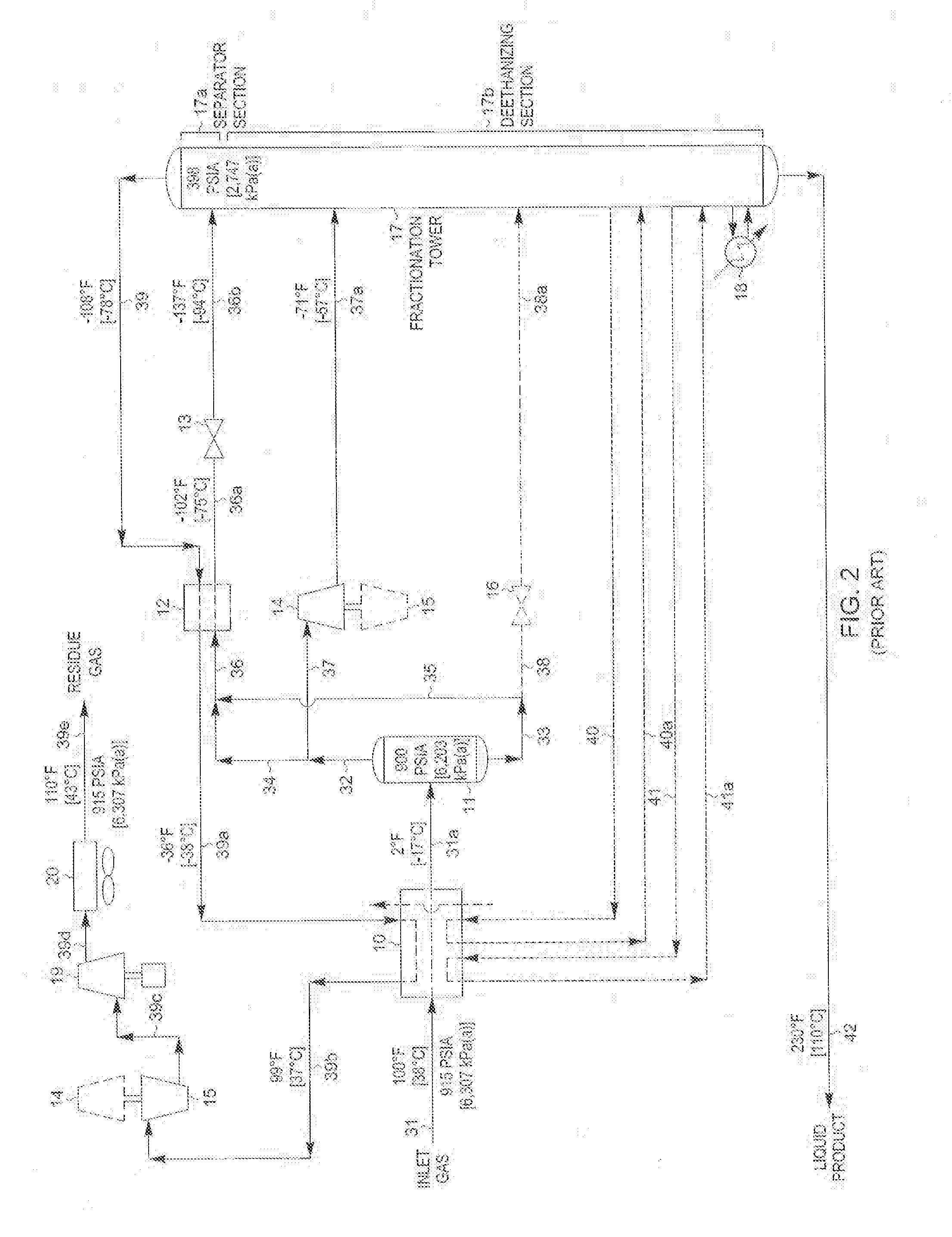
[0041]In those cases where the C2 component recovery level in the liquid product must be reduced (as in the FIG. 2 prior art process described previously, for instance), the present invention offers significant efficiency advantages over the prior art process depicted in FIG. 2. FIG. 4 illustrates a flow diagram of the FIG. 2 prior art process that has been adapted to use the present invention. The operating conditions of the FIG. 4 process have been adjusted as shown to reduce the ethane content of the liquid product to the same level as that of the FIG. 2 prior art process. The feed gas composition and conditions considered in the process presented in FIG. 4 are the same as those in FIG. 2. Accordingly, the FIG. 4 process can be compared with that of the FIG. 2 process to illustrate the advantages of the present invention.

[0042]Most of the process conditions shown for the FIG. 4 process are much the same as the corresponding process conditions for the FIG. 3 process. The main diff...

example 2

[0050]The present invention also offers advantages when product economics favor rejecting only a portion of the C2 components to the residue gas product. The operating conditions of the FIG. 4 process can be altered as illustrated in FIG. 5 to increase the ethane content of the liquid product to the same level as that of the FIG. 3 prior art process. The feed gas composition and conditions considered in the process presented in FIG. 5 are the same as those in FIG. 3. Accordingly, the FIG. 5 process can be compared with that of the FIG. 3 process to further illustrate the advantages of the present invention.

[0051]Most of the process conditions shown for the FIG. 5 process are much the same as the corresponding process conditions for the FIG. 3 process. The main differences are again the disposition of flash expanded substantially condensed stream 36b and column overhead vapor stream 39. In the FIG. 5 process, substantially condensed stream 36a is flash expanded through expansion valv...

example 3

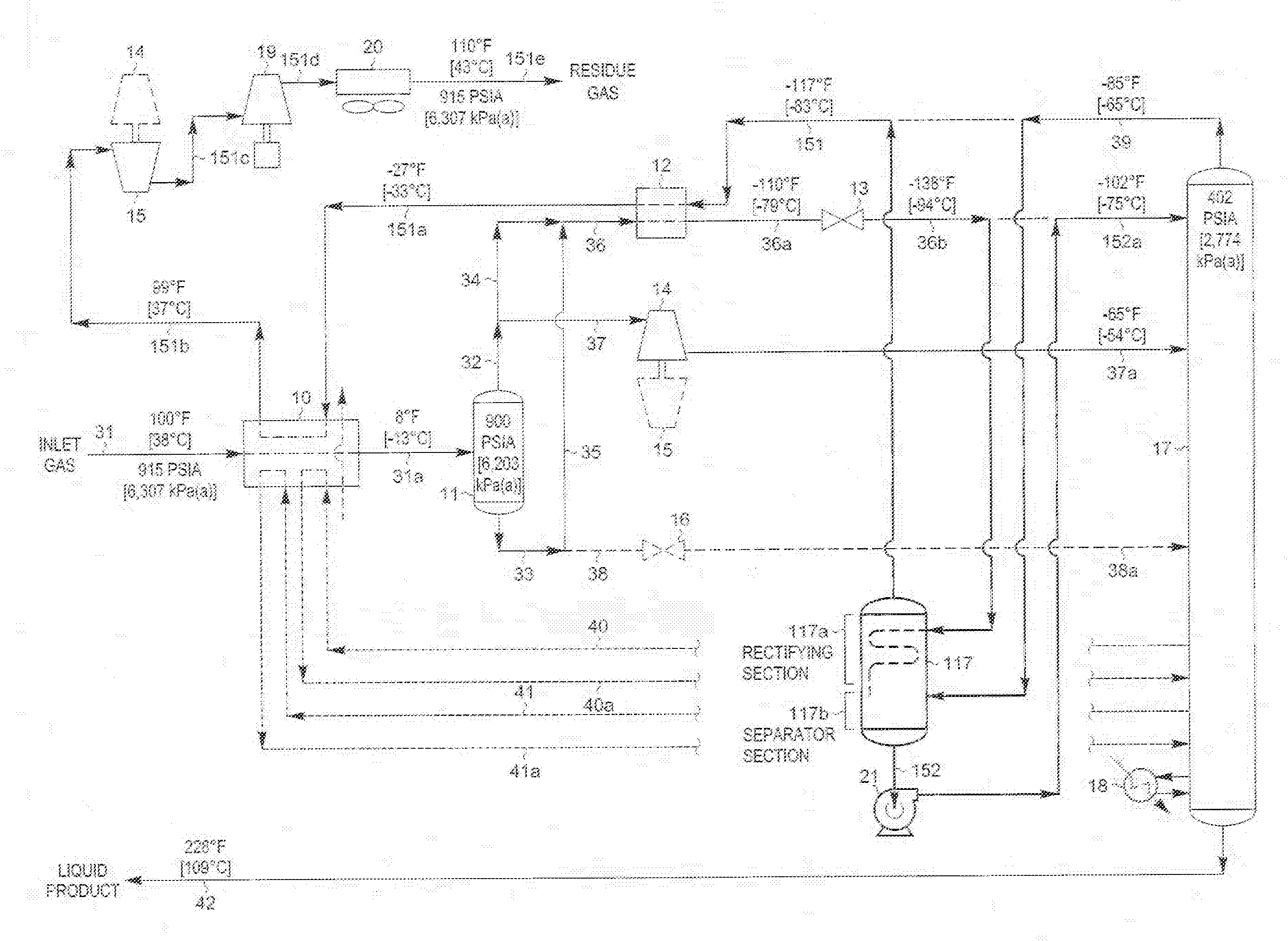
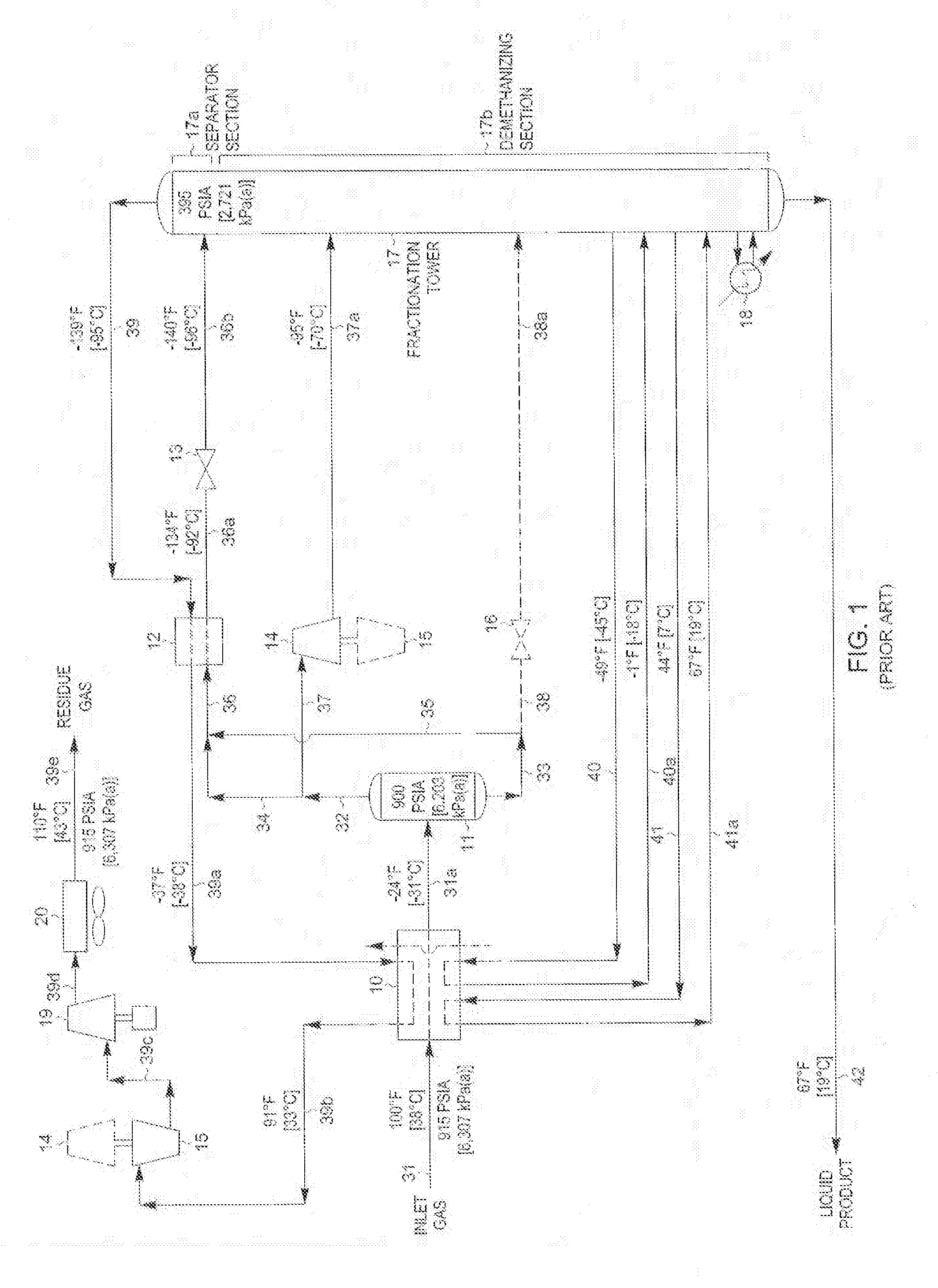
[0056]The present invention can also be operated to recover the maximum amount of C2 components in the liquid product. The operating conditions of the FIG. 4 process can be altered as illustrated in FIG. 6 to increase the ethane content of the liquid product to the same level as that of the FIG. 1 prior art process. The feed gas composition and conditions considered in the process presented in FIG. 6 are the same as those in FIG. 1. Accordingly, the FIG. 6 process can be compared with that of the FIG. 1.

[0057]Most of the process conditions shown for the FIG. 6 process are much the same as the corresponding process conditions for the FIG. 1 process. The main differences are again the disposition of flash expanded substantially condensed stream 36b and column overhead vapor stream 39. In the FIG. 6 process, substantially condensed stream 36a is flash expanded through expansion valve 13 to slightly above the operating pressure (approximately 396 psia [2,731 kPa(a)]) of fractionation to...


PUM

PropertyMeasurementUnit
mole percentaaaaaaaaaa

Abstract

A process and an apparatus are disclosed for a compact processing assembly to improve the recovery of C2 (or C3) and heavier hydrocarbon components from a hydrocarbon gas stream. The preferred method of separating a hydrocarbon gas stream generally includes producing at least a substantially condensed first stream and a cooled second stream, expanding both streams to lower pressure, and supplying the streams to a fractionation tower. In the process and apparatus disclosed, the expanded first stream is heated to form a vapor fraction and a liquid fraction. The vapor fraction is combined with the tower overhead vapor, directed to a heat and mass transfer means inside a processing assembly, and cooled and partially condensed by the expanded first stream to form a residual vapor stream and a condensed stream. The condensed stream is combined with the liquid fraction and supplied to the tower at its top feed point.

Description

BACKGROUND OF THE INVENTION[0001]This invention relates to a process and apparatus for improving the separation of a gas containing hydrocarbons. The applicants claim the benefits under Title 35, United States Code, Section 119(e) of prior U.S. Provisional Application No. 61 / 876,404 which was filed on Sep. 11, 2013. Assignees S.M.E. Products LP and Ortloff Engineers, Ltd. were parties to a joint research agreement that was in effect before the invention of this application was made.[0002]Ethylene, ethane, propylene, propane, and / or heavier hydrocarbons can be recovered from a variety of gases, such as natural gas, refinery gas, and synthetic gas streams obtained from other hydrocarbon materials such as coal, crude oil, naphtha, oil shale, tar sands, and lignite. Natural gas usually has a major proportion of methane and ethane, i.e., methane and ethane together comprise at least 50 mole percent of the gas. The gas also contains relatively lesser amounts of heavier hydrocarbons such a...

Claims


Application Information

Patent Timeline
Patent Type & Authority Applications(United States)
IPC IPC(8): C07C7/04F25J1/00
CPCF25J1/0022C07C7/04F25J3/0233F25J3/0238F25J3/0242F25J2200/02F25J2200/70F25J2200/74F25J2200/80F25J2205/04F25J2235/60F25J2270/90F25J2290/40F25J2290/80F25J3/0209F25J2240/02F25J2210/06F25J2215/04F25J2215/60F25J2230/20F25J2230/60F25J2240/40F25J2290/12
Inventor HUDSON, HANK M.WILKINSON, JOHN D.LYNCH, JOE T.MILLER, SCOTT A.CUELLAR, KYLE T.JOHNKE, ANDREW F.LEWIS, W. LARRY
Owner S M E PROD
Why Eureka
Try Eureka