Method of vaccine delivery via microneedle arrays
a microneedle array and vaccine technology, applied in the field of vaccine delivery, can solve problems such as poor patient complian
- Summary
- Abstract
- Description
- Claims
- Application Information
AI Technical Summary
Benefits of technology
Problems solved by technology
Method used
Image
Examples
example 1
General Process for Array Casting
[0103]The mold to be used to form a microneedle array is cleaned with water and dried in an incubator. The mold is then placed in a Petri dish. One dispenses a small amount of formulation, for example, 20 μL, on the mold. The formulation may contain, for example, 25% BSA (bovine serum albumin), 20% polyvinyl alcohol USP, 27% trehalose, and 28% maltitol in water solvent, such that the formulation has, for example, 20% solids content as applied. The formulation is spread manually over the mold using a transfer pipette with a trimmed tip. The formulation is then vortexed, for example for five seconds, using a commercial vibrating instrument to even out the formulation. The mold with the formulation covering it is placed in a pressure vessel under 1 atm for about 10 minutes. Pressure is then removed. The mold is placed in the incubator at a temperature of 32° C., for about 1 hr. The array may then be demolded, for example using double-sided adhesive tape...
example 2
General Process for Casting Two-Layer Arrays
[0104]Following the drying step of Example 1, an additional layer is cast on the mold using similar procedures. The additional layer may, for example, consist of 75 μL, of 20 wt % Eudragit EPO in a 3:1 mixture of ethanol and isopropyl alcohol. The additional layer may be spread out, for example, using a glass slide. The mold is placed in a pressure vessel and pressurized at 1 atm for 2 minutes. The pressure is released and the mold is allowed to dry in the pressure vessel for an additional five minutes, without disturbing. The mold is again dried in the incubator for 1 hr at 32° C., and then demolded.
example 3
Microneedle Arrays Comprising RPA
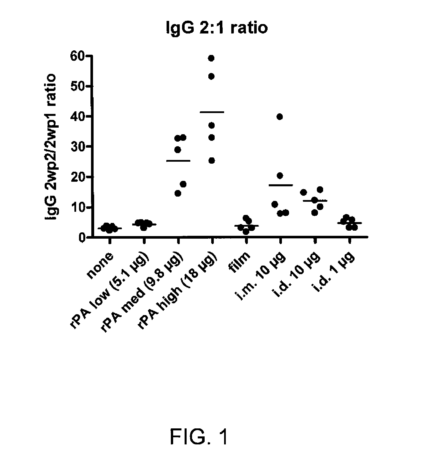
[0105]For an immunogenicity study in a rat model, microneedle structures containing an antigen (rPA, recombinant protective antigen from Bacillus anthracis) were fabricated from components that dissolve when they enter the skin, releasing antigen directly into the epidermis. The devices were produced by introduction of an aqueous casting solution to a micromold to make a microneedle array with 200 μm tall, 6-sided structures, at about 700 structures per cm2, total area approximately 2 cm2.
[0106]More specifically, the microneedle arrays were prepared with the following procedure. A 24 / 17 mm diameter PET (polyethylene terephthalate) ring, approximately 200 μm thick, with a PVP+PEG (polyvinylpyrrolidone+polyethylene glycol) adhesive layer, was attached to the microneedle mold base to form a boundary. Fifty μL of formulation was pipetted and spread. This was vortexed for 5 sec to homogenize the liquid layer and placed in a pressure cooker at 1 bar for 10...
PUM
 Abstract
Description
Claims
Application Information
 - R&D
- Intellectual Property
- Life Sciences
- Materials
- Tech Scout
- Unparalleled Data Quality
- Higher Quality Content
- 60% Fewer Hallucinations
Browse by: Latest US Patents, China's latest patents, Technical Efficacy Thesaurus, Application Domain, Technology Topic, Popular Technical Reports.
© 2025 PatSnap. All rights reserved.Legal|Privacy policy|Modern Slavery Act Transparency Statement|Sitemap|About US| Contact US: help@patsnap.com

