Cooking material dispensing method and dispensing system

a technology of dispensing method and dispensing system, which is applied in the field of cooking to achieve the effects of convenient, rapid and simplified cooking process, accurate movement, and effective avoiding the contamination of the dish by the feeding devi

Active Publication Date: 2015-05-14
LIU XINYU
View PDF35 Cites 12 Cited by
  • Summary
  • Abstract
  • Description
  • Claims
  • Application Information

AI Technical Summary

Benefits of technology

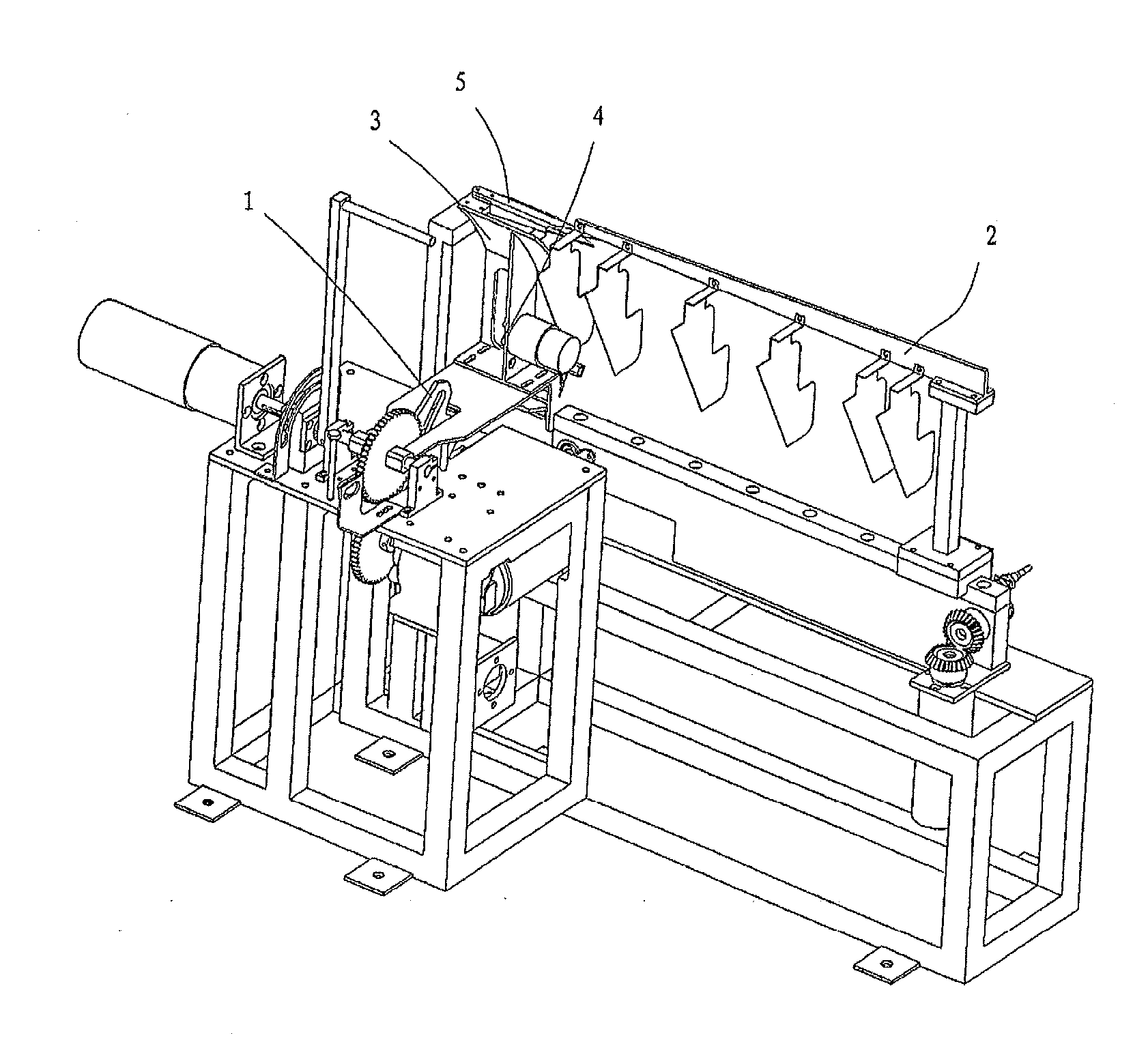
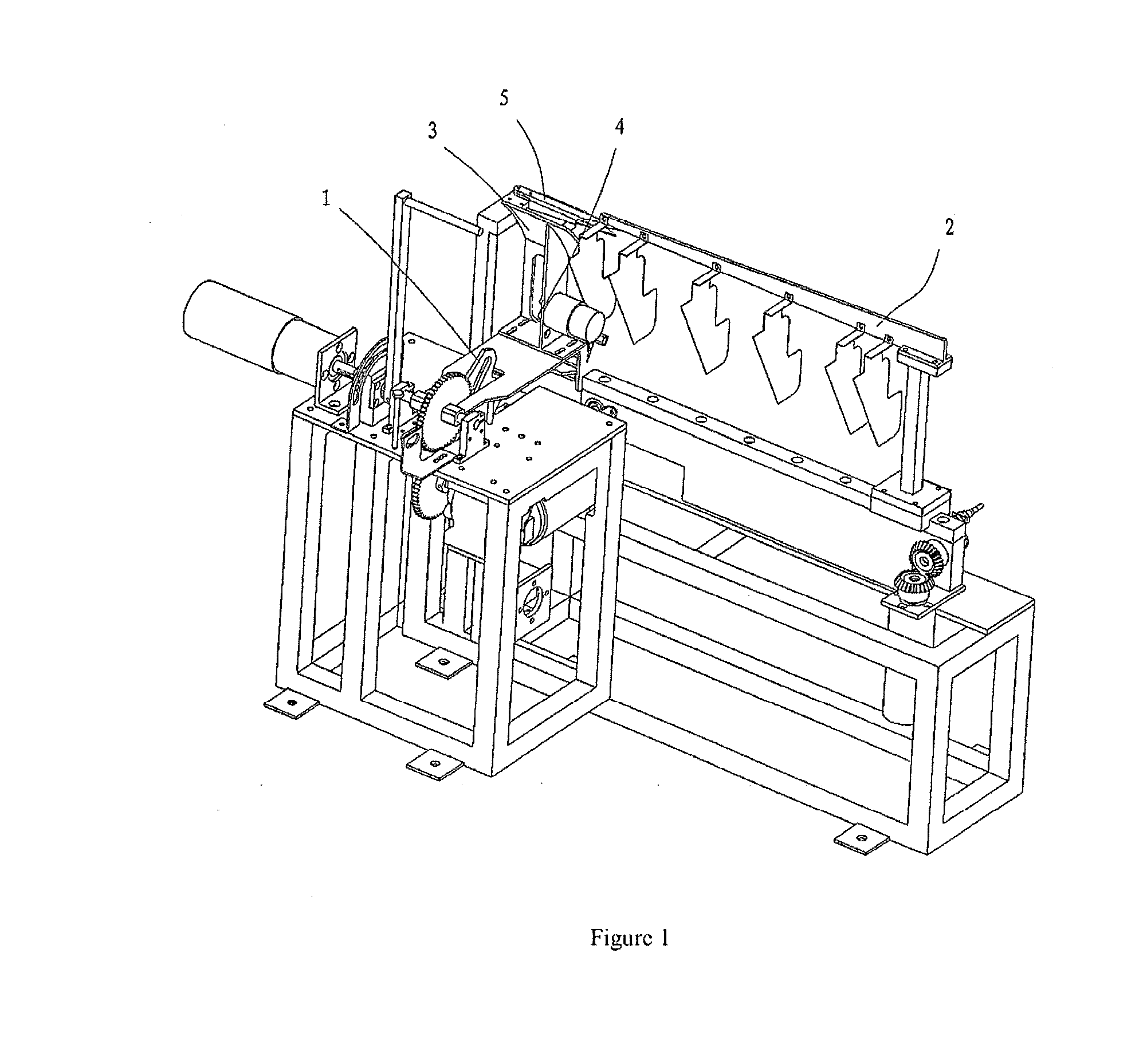
[0036]The feeding method of the present invention is able to achieve automatic cooking and processing, using bags to contain cooking ingredients. The feeding device based on the feeding method of the present invention integrates the means for clamping, conveying, toppling or turning-over, and is capable of automatically completing the feeding process by clamping, conveying and toppling / turning-over the ingredient bag. By arranging different working stations, each mechanism of the device can be separately arranged and reasonable layouts can be given to suit actual needs, so that the clamped bag can be accurately moved to reach the desired feeding position by successively conducting certain predetermined movements, so as to avoid the mutual interference of the complicated structures surrounding the cooking pot, and to provide operating space for the stir-fry of cooking ingredients in the pot, to provide some room for the movement of the pot, and to ensure that the ingredients do not spill and / or outflow from the ingredient bag when it is being clamped and conveyed and that the opening of the ingredient bag may be restored to face upward after the feeding, effectively preventing the residuals from staining the surrounding area of the system. In the meantime, the feeding device itself is not inclined to get stained easily, therefore effectively avoiding the feeding device from contaminating the dish. This feeding device is particularly desirable in a cooking environment which is difficult to clean, providing a convenient, swift and simplified cooking process.
[0037]The present invention uses bags to hold ingredients, and compared with the use of cartridges, the present invention is cost-effective, and is able to achieve the automatic production, packaging and conveyance of ingredients, and at the same time, without a complicated tearing mechanism, the system of the present invention further saves design cost and production cost. In the feeding process, the ingredients inside the ingredient bag are completely emptied out by turning-over, compressing and shaking the ingredient bag.

Problems solved by technology

However, the pace of life has become increasingly fast.
Coming home fatigue and exhausted after a hard day's work, people are increasingly unwilling to prepare meals and hope to free themselves from heavy housework so that they may pursue more leisure activities.
More importantly, the cooking process is not only labor intensive, but the long hours working among the heat and fume in the kitchen also leads to various kitchen diseases.
Robots have also appeared to perform some tedious cooking tasks in the kitchen.
However, since the cartridge has a length and a width, and the packaging film are generally sealed around the cartridge, and thus using the relative movement produced between the film clamper and the cartridge to open the cartridge may result in incomplete or unreliable opening of the packaging film.
In addition, the production costs of the cartridge and packaging film is actually quite high.
However, it is also disadvantageous in that the ingredient cartridge is not sealed and thus places certain requirements on the cooking environment, and does not facilitate the preservation, the automatic processing, the packaging and transportation of the ingredients prior to the actual cooking.
(1) The complex structure of the entire cooking system is inclined to result in the mutual interferences of different mechanisms.
(2) Since the pot is a component that requires frequent cleaning, arranging two conveyor belts and a cutting tool over the pot makes its cleaning troublesome.
(3) It is also quite complicated and troublesome to assemble and disassemble the ingredient bag clamped by the conveyor belts.
(4) During the entire process from the start of the feeding process to the completion of the feeding, the ingredient bag remains over the pot, and it is thus inclined to be affected by the continuous thermal radiation or smog generated when the pot is being heated, and the quality of the cooking is thus impaired. In addition, in case that the ingredient bag fails to pour the ingredients completely into the pot, it is possible that the ingredients intermittently leak into the pot and thus would also seriously impair the quality of the cooking.
(5) After being cut, the ingredient bag would have a movement similar to pendulum movement, and hence the ingredients in the ingredient bag are unable to fall into a desired area. The desired area refers to the appropriate position that the cooking ingredients should be located in the cooking pot according to the object point of the cooking utensils, the requirements of the cooking technique and the actual needs of the cook. The appropriate position is within the desired area, and it means that when the cooking ingredients are in this position, the ingredients can be heated and / or stirred in an effective, uniform and / or desirable manner. Usually the appropriate position locates within an inner area around the heated center of the cooking pot, or within an area covered by a heat-transfer medium (such as oil) and the like, and should be smaller than the entire inner area of the cooking pot. One example is the Chinese wok. When the heat source is located in the central portion of the wok, the area near the central portion (e.g. if with the central point of the wok as the center of a circle, it is an area that has a diameter of about 5-15 cm extending from the center of the circle, or a smaller area) is the appropriate position. Outside this area, the temperature of the wok decreases rapidly, and may thus become inappropriate position. The appropriate position can, of course, be the entire range of the cooking pot. For example when using a small wok or a special shaped wok, or when the wok needs to be turned-over in a wide angle (e.g., 180-degree turn, 360 degree turn of the wok etc.), or when the entire wok is evenly heated. The so-called inappropriate position is the place where the cooking ingredients are difficult to or even can not be turned-over or stirred evenly and effectively by a turning-over means or a stirring means, the place where the cooking ingredients are difficult to or even can not go back to the appropriate position, the place where the cooking ingredients are difficult to or even can not be gathered to the desired area in the cooking pot, the place where the cooking ingredients are difficult to or even can not be heated evenly and effectively, and / or the place where it is not advantageous to a cooking process. For example, such an inappropriate position could be a blind area where a turning-over means or a stirring means can not reach, an area where a good turning-over effect can not be obtained although a turning-over means or a stirring means can reach there, an area which is beyond the turning-over / stirring range or even out of the cooking pot, or an area where the control system of a cooking utensil or a cooking machine is difficult to or can not detect the existence of the cooking ingredients although it is in the area where it could be turned-over or stirred but it fails to be turned-over or stirred. When the appropriate position extends to the whole inner area of the cooking pot then the inappropriate position is the area which is out of the cooking pot. The quality of dish can be impaired seriously under the foresaid circumstances, and it may even lead to the failure of the cooking.
(6) The area over the pot is an important area for conducting various operations. If the feeding means is disposed over the pot, it will reduce the operation space of other means, e.g. a mixing means. In addition, if disposed over the pot, the feeding means would easily be grimed by the fume and damaged by the heat. If the feeding means grimed, it would be difficult to clean the grime and the grime may drop into the pot and contaminate the dish.
However, the above arrangement has the following drawbacks: Firstly, only by gravity, the ingredients are hardly emptied out.
Furthermore, this rotational feeding manner requires a complicated structure, and it is difficult to manufacture, assemble, clean the multiple parts of the structure and it is difficult to fix the package.
Secondly, because its opening means is provided at the lower end of the package fixing means, the ingredients in the package may easily spill onto the opening means and stain the opening means.
Thirdly, since the desired position on which the ingredients should fall is somewhere near the center of the pot covered with oil, if the ingredients fall onto somewhere without oil or with very little oil, such as on the periphery of the pot, those ingredients would stick to the pot, and they would be out of the reach of the stirring means.
Furthermore, with this arrangement, the surrounding area of the pot is very crowded and it would not be easy to clean these components.

Method used


Image

  • Cooking material dispensing method and dispensing system
  • Cooking material dispensing method and dispensing system
  • Cooking material dispensing method and dispensing system

Examples


third embodiment

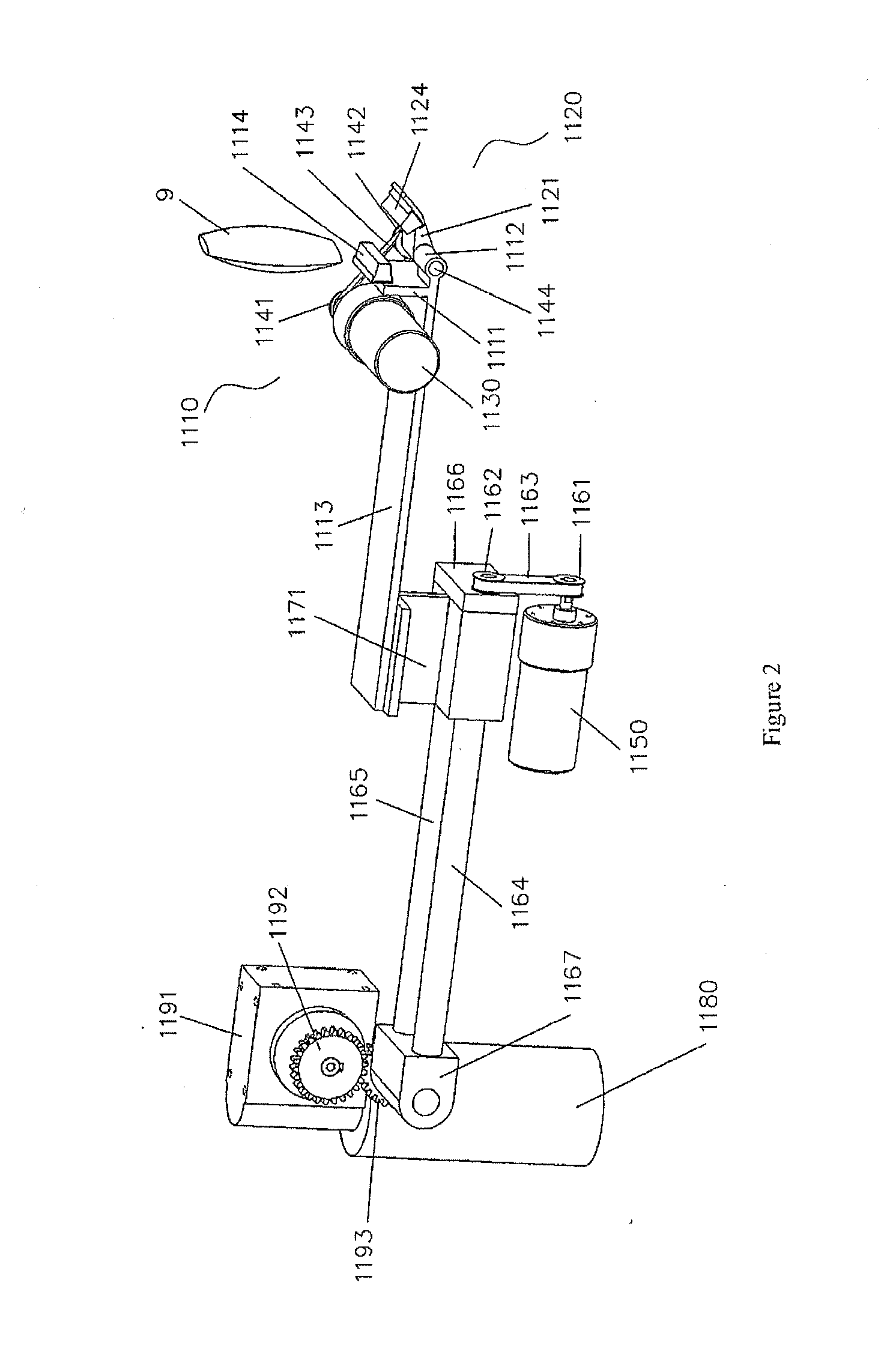
[0136]The clamping-toppling and conveying mechanism of the present example is the combinations of the various mechanisms of the feeding device 1, comprising: a clamping toppling means for clamping the bag and limiting the state of the bag when it is being clamped, and for automatically pouring ingredients inside the bag to the cooking pot; and an inter-station conveying means for moving the bag which is clamped by the clamping toppling means between the clamping station and the feeding station.

[0137]Further, the clamping toppling means comprises a clamp, a clamping toppling driver and a clamping toppling route converter. The clamp is used for clamping or releasing the bag; the clamping toppling route converter is disposed between the clamping toppling driver and the clamp, used for converting the torque outputted by the clamping toppling driver when the clamp is at the clamping station into a clamping torque for driving the clamp to grip the bag and a releasing torque for releasing ...

fourth embodiment

[0148]The clamping and conveying-toppling mechanism of the present example is the combinations of the various mechanisms of the feeding device 1, comprising: a bag clamping means for clamping the bag and for limiting its state, and a conveying-toppling means used for moving the bag which is clamped by the bag clamping means between the clamping station and the feeding station and for automatically pouring ingredients inside the bag to the cooking pot. The bag clamping means comprises a clamp, a clamping driver and a clamping route converter. The clamp is disposed at the clamping station and used for clamping or releasing the bag. The clamping route converter is disposed between the clamping driver and the clamp, used for converting the torque outputted by the clamping driver into a clamping torque for driving the clamp to grip the bag and used for converting the torque outputted by the clamping driver into the releasing torque for releasing the bag.

[0149]Referring now to FIGS. 14-17...

sixth embodiment

[0181]Reference now is made to FIGS. 22-26. the feeding device 1 in the present invention can also be a clamping and toppling mechanism, comprising: a bag clamping means for clamping and limiting the bag containing cooking ingredients, an ingredient toppling means for automatically pouring ingredients inside the bag into the cooking pot, and a bag cutting means for cutting the upper end of the bag before pouring out the ingredients.

[0182]The bag clamping means comprises a clamp, a clamping driver and a clamping route converter. The clamp is disposed at the clamping station for clamping or releasing the bag. The clamping route converter is used for converting the torque outputted by the clamping driver into the clamping torque for activating the clamp to grip the bag or into the releasing torque for releasing the bag.

[0183]Referring again to FIGS. 22-26, the clamping driver is a clamping drive motor 1525. The bag clamping means comprises a fixed clamping head 1536 and a movable clamp...


PUM


Abstract

Disclosed are a cooking material dispensing system and dispensing method. The dispensing method comprises the following steps: setting a material bag (9) clamping station in a position near a cooking pot opening but outside the range of the pot opening, and clamping the material bag (9) containing a cooking material at the material bag (9) clamping station; confining the material bag (9), such that the material bag (9) is kept in a clamped state to control the deformation thereof during the dispensing procedure; flipping and/or tipping the material bag (9), and when in a position near the cooking pot opening, dispensing the cooking material in the material bag (9) into the cooking pot; and once the cooking material has been dispensed, shifting the material bag (9) from the range of the cooking pot opening and releasing the clamping of the material bag (9). The cooking material dispensing system comprises a dispensing device capable of clamping, confining, and transferring the material bag (9) and flipping the opened material bag and/or tipping the cooking material into the cooking pot. The dispensing system and dispensing method take a material packaged in the material bag (9) and can accurately move the material bag (9) into the dispensing position, making the cooking process convenient, fast and simple, and the entire process will not be contaminated.

Description

FIELD OF THE INVENTION[0001]The present invention relates to the technical field of cooking. More particularly, the present invention relates to a feeding method for inputting cooking ingredients contained in an ingredient bag into a cooking pot under the control of a control system and a feeding system based on this feeding method.BACKGROUND OF THE INVENTION[0002]With the continuous progress and development of society, people have become increasingly demanding on the quality of their life, and increasing attention has also been made to their diets. However, the pace of life has become increasingly fast. Coming home fatigue and exhausted after a hard day's work, people are increasingly unwilling to prepare meals and hope to free themselves from heavy housework so that they may pursue more leisure activities.[0003]In the traditional cooking process, the cook does all things, from selecting and matching of cooking ingredients, inputting the ingredient into the pot, cooking the food, r...

Claims


Application Information

Patent Timeline
Patent Type & Authority Applications(United States)
IPC IPC(8): B65B69/00A47J43/00A47J36/34
CPCB65B69/0008A47J43/00A47J36/34A47J37/045B65B69/005B65B69/0075B65G47/248B65G47/252A23L3/001B01F31/00B01F33/35B01F35/513
Inventor LIU, XINYUYAN, PING
Owner LIU XINYU
Why Eureka
Try Eureka