Linear motor and stage apparatus

Active Publication Date: 2015-05-21
SHANGHAI MICRO ELECTRONICS EQUIP (GRP) CO LTD
View PDF3 Cites 31 Cited by
  • Summary
  • Abstract
  • Description
  • Claims
  • Application Information

AI Technical Summary

Benefits of technology

[0027]In the linear motor and stage apparatus of this invention, the coil unit includes a first coil array and a second coil array arranged in a stacked manner in the Z-axis direction and the first and second coil arrays are staggered from each other by a distance of ΔP in the Y-axis direction, and ΔP is so set that when the coil unit is provided with a desired electrical current from a control system, the coil unit generates a control force along the Y-axis direction, another control force along the Z-axis direction, and a moment about the X-axis direction. Arranging the first and second coil arrays into two separate layers enables the generation of a desirable vertical levitation force, and staggering the two layers of the coil arrays by a certain distance from each other can provide a desirable control moment with ripple force that may be caused by tilt or other factors being canceled out to eliminate any torsional moment, thus achieving precision positioning. Further, by incorporating the linear motor, the stage apparatus is capable of providing a driving force in a certain horizontal direction and a vertical levitation force, with a simple structure not including any air levitation mechanism, as well as easy operations.
[0028]Additionally, in the linear motor and stage apparatus of this invention, each of the first and second magnet arrays is composed of first-type magnets, second-type magnets and third-type magnets arranged along the Y-axis direction in a similar periodically alternating manner of a Halbach array, each of the third-type magnets being interposed between a corresponding one of the first-type magnets and an adjacent one of the second-type magnets; the first-type magnets and second-type magnets are arranged alon

Problems solved by technology

The high-speed, high-acceleration and high-precision-positioning requirements of the photolithographic apparatus are conflicting.
However, as the reference has not considered the ripple force that may be caused by tilt or other factors, this motor is still incapable of satisfactory precision positioning of the stage.
Moreover, the used laterally aligned cuboid-shaped magnets may cause magnetic flux leakage at the magnetic yoke and thus precision control difficulties and insufficient control forces.
The high-speed, high-acceleration and high-precision-positioning requirements of the photolithographic apparatus are conflicting, and to increase its scanning speed requires more powerful motors.
However, since such structure currently adopts an air-bearing-based drive technology, it is not able to achieve the reconciliation of multiple-degree-of-freedom movement and actuator integration.
This results in a large moving mass of the system and hence a large driving force, as well as significant residual vibration caused by a proportionally large reaction force to the driving force which is detrimenta

Method used


Image

  • Linear motor and stage apparatus
  • Linear motor and stage apparatus
  • Linear motor and stage apparatus

Examples


Example

EMBODIMENT 1

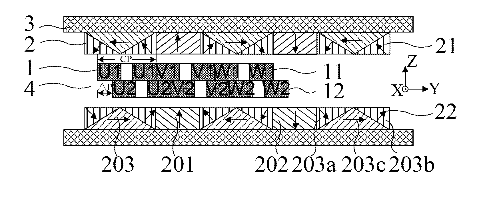
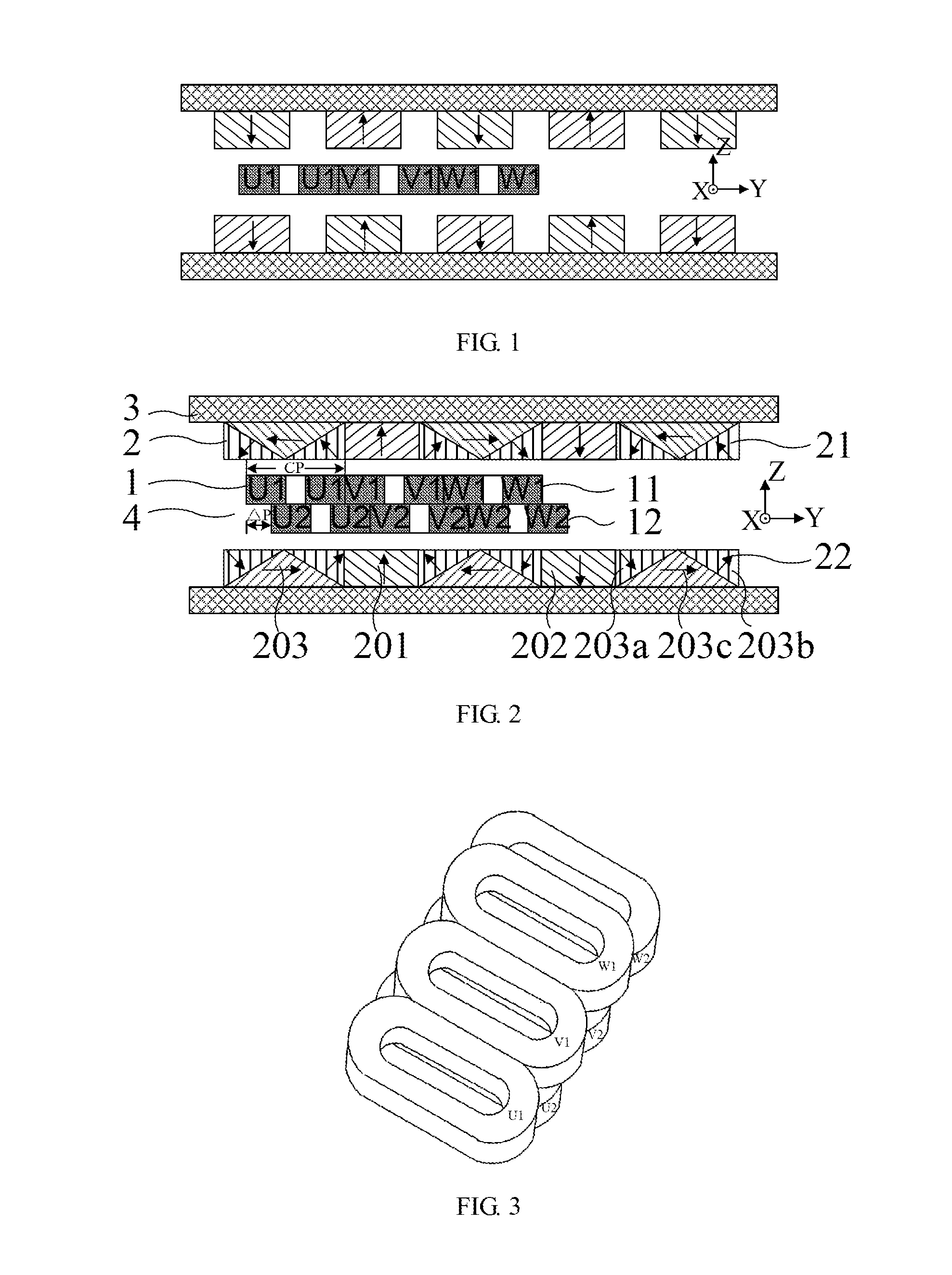
[0050]Referring to FIG. 2, a linear motor constructed in accordance with this embodiment includes a magnet unit 2, a coil unit 1, a magnet fixing member 3, i.e., a magnetic yoke and a control system (not shown). The magnet fixing member 3 appears U-shaped, when viewed from one side of the linear motor (i.e., the XZ plane in this embodiment), and serves to support the magnet unit 2. The magnet unit 2 includes two magnet arrays, a first magnet array 21 and a second magnet array 22, arranged on the magnetic yoke, symmetrically and in parallel to each other. In other words, the magnet unit 2 includes the first and second magnet arrays 21 and 22 which are respectively arranged on the parallel inner walls of the magnet fixing member 3. The coil unit 1 is disposed in a magnetic gap 4 formed between the two magnet arrays, i.e., disposed in a magnetic gap 4 formed between the first and second magnet arrays 21 and 22, and the control system is configured to supply an electrical cu...

Example

EMBODIMENT 2

[0063]Referring to FIG. 14, this embodiment differs from embodiment 1 in that:

[0064]the first, second and third prismatic magnets 203a, 203b and 203c have cross sections in the Y-Z plane in the shapes of a right triangle, an isosceles trapezoid and a right triangle, respectively. Each of the first and second magnet arrays 21 and 22 is composed of third-type magnets 203 of the above-mentioned structure, first-type magnets 201, and second-type magnets 202. The linear motor of this embodiment offers the same advantages of: generating a desirable vertical levitation force; providing a desirable control moment with ripple force that may be caused by tilt or other factors being canceled out to eliminate any torsional moment, thus achieving precision positioning; creating an augmented vertical magnetic flux and hence increased horizontal driving force; and having less magnetic flux. leakage.

Example

EMBODIMENT 3

[0065]Referring to FIG. 15, this embodiment differs from embodiment 1 in that: the first, second and third prismatic magnets 203a, 203b and 203c have cross sections in the Y-Z plane in the shapes of a right trapezoid, an isosceles triangle and a right trapezoid, respectively, and the two right trapezoids share a common side. The first and second magnet arrays 21 and 22, each composed of the third-type magnets 203 of the above-mentioned structure, first-type magnets 201 and second-type magnets 202, also have the advantage of less magnetic flux leakage. The linear motor of this embodiment also offers the same advantages of: generating a desirable vertical levitation force; providing a desirable control moment with ripple force that may be caused by tilt or other factors being canceled out to eliminate any torsional moment, thus achieving precision positioning; creating an augmented vertical magnetic flux and hence increased horizontal driving force; and having less magneti...


PUM


Abstract

A linear motor includes a magnet unit and a coil unit. The magnet unit includes two magnet arrays oppositely parallel and symmetrically located on a magnetic yoke: a first and a second magnet array. The coil unit is disposed in a magnetic gap between the two magnet arrays. In a spatial rectangular coordinate system defined by X, Y and Z axes, the coil unit includes a first and a second coil array arranged in a stacked manner in the Z-axis direction and staggered from each other by a distance of ΔP in the Y-axis direction. ΔP satisfies: when a control system charges the coil unit with a desired current, the coil unit generates a control force along the Y-axis direction, another control force along the Z-axis direction, and a moment about the X-axis direction, which may reduce a magnetic flux leakage and provide higher driving forces, making the linear motor generate required three degrees-of-freedom control force or control torque, and further improve vertical and horizontal magnetic fluxes in the magnet array.

Description

TECHNICAL FIELD[0001]The present invention relates to the field of photolithography, and in particular, to a linear motor and a stage apparatus.BACKGROUND[0002]With the improvement of photolithographic technology and the rapid development of semiconductor industry, the performance of a photolithographic apparatus can be assessed on the four fundamental characteristics, i.e., critical dimension (CD) uniformity, focal-depth or focus accuracy, overlay accuracy, and throughput. In order to improve the critical dimension uniformity, a wafer or a mask stage needs to improve its horizontal positioning precision. In order to improve the focal-depth accuracy, the wafer or mask stage needs to improve its vertical positioning precision. In order to improve the overlay accuracy, the wafer or mask stage needs to have an improved internal model which can enhance its dynamic positioning characteristics. In addition, considering the photolithographic apparatus is generally required to increase its ...

Claims


Application Information

Patent Timeline
IPC IPC(8): H02K41/03
CPCH02K41/031
Inventor WU, LIWEICHEN, QINGSHENGYAN, LANZHOU
Owner SHANGHAI MICRO ELECTRONICS EQUIP (GRP) CO LTD
Why Eureka
Try Eureka