Attenuation circuit for an energy storage device and method for attenuating oscillations of the output current of an energy storage device

Inactive Publication Date: 2015-05-21
ROBERT BOSCH GMBH
View PDF4 Cites 5 Cited by
  • Summary
  • Abstract
  • Description
  • Claims
  • Application Information

AI Technical Summary

Benefits of technology

[0013]One concept of the present invention consists in superimposing a compensation current on an output current of an energy storage device with modular energy supply strings comprising a series circuit of energy storage modules, with the result that resonances as a result of current fluctuations of a variable current source fed by the energy storage device are damped. In this case, output currents of the energy storage device are detected and compensation currents are actively generated in the energy storage device itself depending on the output currents detected or the fluctuations in the output currents. At least one of the energy storage modules of the energy storage device can be used for this purpose, which module is operated in a pulse-width-modulated actuation operating mode in order to realize the compensation currents. The compensation currents matched flexibly in terms of their amplitude in this case serve to actively damp possible resonances.
[0014]As a result of this damping, on-board power supply system resonances can be damped without any additional losses in the power path. By virtue of inherent closed-loop control via the current feedback loop, it is advantageously possible to match the damping to the position of the resonance frequency and the magnification factor of the resonant circuit, irrespective of the instantaneous operating state of the energy storage device. In particular, measurement of the resonant frequency of the energy storage device is no longer necessary. Changes which can occur, for example, owing to aging or changes in the system topology, for example owing to longer high-voltage lines, during operation of the energy storage device are also automatically and flexibly compensated for by the damping circuit.
[0015]By virtue of the active closed-loop control, a degree of damping can advantageously be selected by an adjustable frequency range. The design and control parameters for the damping circuit are in this case independent of the instantaneous value for an intermediate circuit capacitor connected to the energy storage device.
[0016]The damping

Problems solved by technology

A series circuit comprising a plurality of battery modules is associated with the problem that the entire string fails when a single battery module fails.
Such a failure of the energy supply string can result in failure of the entire system.
Furthermore, temporarily or permanently occurring reductions in power of a sin

Method used


Image

  • Attenuation circuit for an energy storage device and method for attenuating oscillations of the output current of an energy storage device
  • Attenuation circuit for an energy storage device and method for attenuating oscillations of the output current of an energy storage device
  • Attenuation circuit for an energy storage device and method for attenuating oscillations of the output current of an energy storage device

Examples


Embodiment Construction

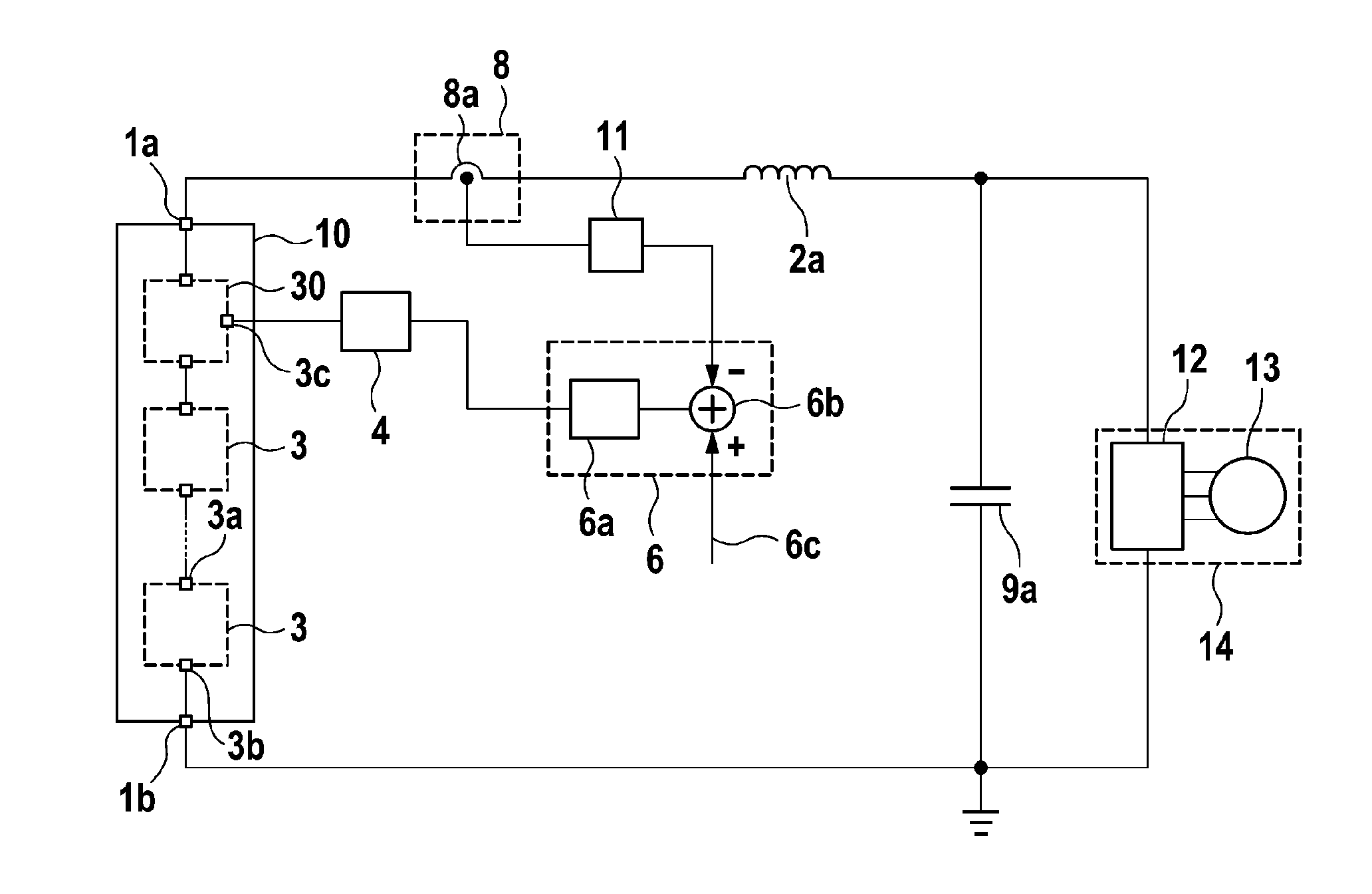
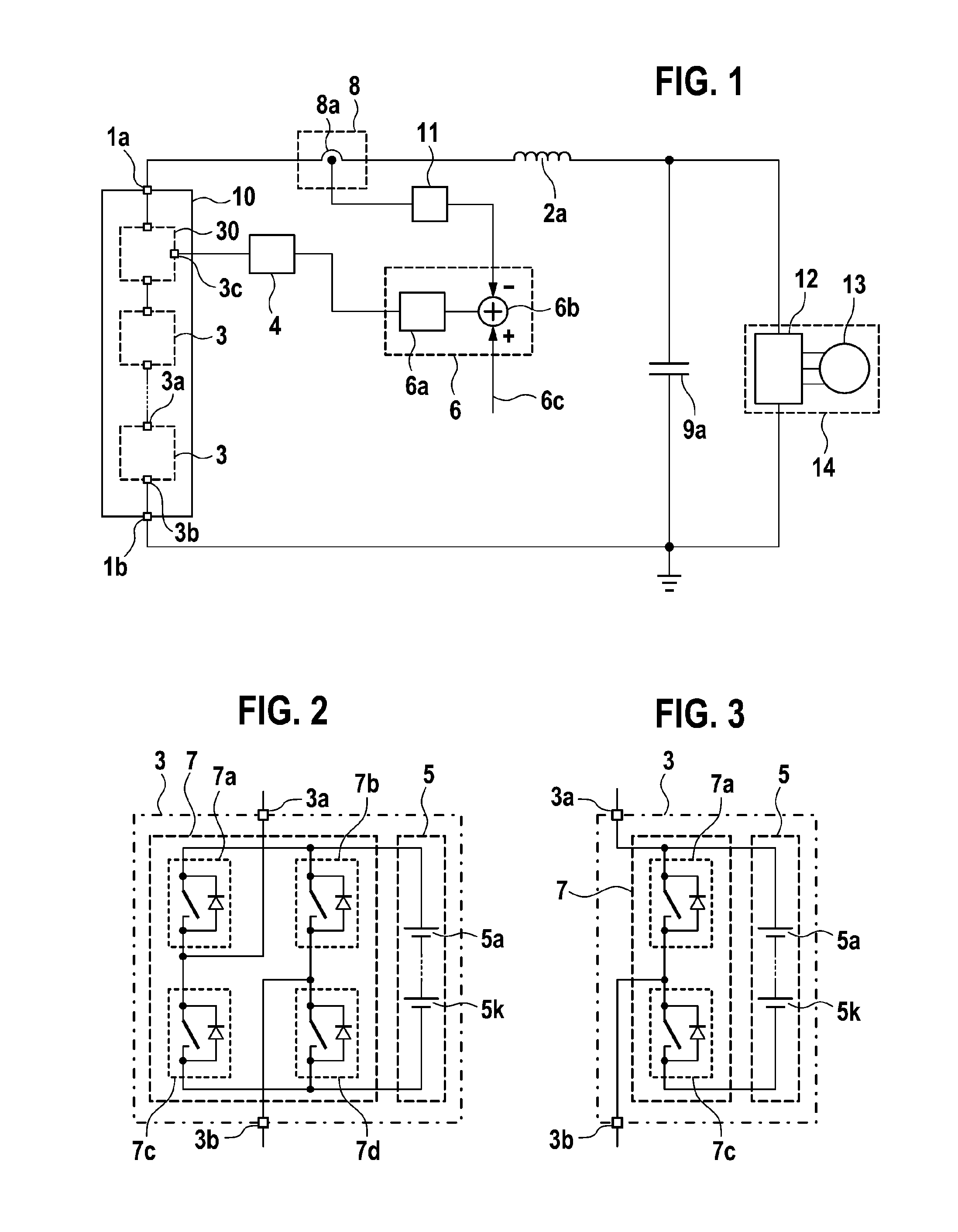
[0027]FIG. 1 shows a system which comprises an energy storage device 10 for providing a supply voltage by energy storage modules 3 connected in series in an energy supply string between two output connections 1a, 1b of the energy storage device 10. The energy storage device 10 can alternatively also have a plurality of energy supply strings connected in parallel. The energy storage device 10 acts as current source of a variable output current owing to the actuation of the energy storage modules 3.

[0028]The energy storage device 10 can in this case be coupled to an input connection of a DC voltage intermediate circuit 9a via a storage inductance 2a at the output connection 1a of the energy storage device 10. The storage inductance 2a can be implemented, for example, by a concentrated component, such as a current-limiting inductor, or a plurality of distributed components. Alternatively, parasitic inductances of the energy storage device 10 can also be used as storage inductance 2a. B...


PUM


Abstract

The invention relates to an attenuation circuit for an energy storage device having one or more energy storage modules which are connected in series in one or more energy supply lines and have at least one energy storage cell and a coupling device which has a multiplicity of coupling elements and is designed to selectively switch or bridge the energy storage cell in the respective energy supply line. The attenuation circuit comprises a current detection device which is designed to detect an output current of the energy supply lines or of the energy storage device and to generate an output current signal dependent on the output current, a control circuit which is coupled to the current detection device and is designed to control the output current signal to a desired current signal and to output a corresponding current control signal, and a pulse width modulation device which is coupled to the control circuit and is designed to control the coupling device of at least one of the energy storage modules in a clocked manner on the basis of the current control signal.

Description

BACKGROUND OF THE INVENTION[0001]The invention relates to a damping circuit for an energy storage device and to a method for damping oscillations of the output current of an energy storage device, in particular for battery converter circuits for supplying voltage as a variable current source for loads occurring such as, for example, electric machines in drive systems of electrically operated watercraft or land vehicles.PRIOR ART[0002]It would appear that, in the future, electronic systems which combine novel energy storage technologies with electric drive technology will be used increasingly both in stationary applications, such as wind turbines or solar power installations, for example, and in vehicles such as hybrid or electric vehicles.[0003]In order to feed alternating current into an electric machine, a DC voltage provided by a DC voltage intermediate circuit is conventionally converted into a three-phase AC voltage via a converter in the form of a pulse-controlled inverter. Th...

Claims


Application Information

Patent Timeline
IPC IPC(8): H02J7/00
CPCH02J2007/0067H02J7/0065H02J1/02H02J7/0024H02M1/14H02J2207/20H02M7/4835H02J2310/40H02M7/49
Inventor KESSLER, MARTIN
Owner ROBERT BOSCH GMBH
Why Eureka
Try Eureka