Clock signal generation circuit, detection device, sensor, electronic apparatus, and moving object

a clock signal and detection device technology, applied in the direction of optical radiation measurement, pulse technique, instruments, etc., can solve the problems of increasing the layout area of the circuit device, increasing and unable to achieve high-speed operation of the control section. , to achieve the effect of suppressing an increase in current consumption and circuit siz

Active Publication Date: 2015-05-28
SEIKO EPSON CORP
View PDF4 Cites 12 Cited by
  • Summary
  • Abstract
  • Description
  • Claims
  • Application Information

AI Technical Summary

Benefits of technology

[0010]An advantage of some aspects of the invention is to provide a clock signal generation circuit, a detection device, a sensor, an electronic apparatus, a moving object, and so on capable of realizing the temperature compensation of the oscillation frequency while suppressing an increase in current consumption and circuit size, and so on.

Problems solved by technology

However, in the related art described above, a reference voltage generation circuit, one or more operational amplifiers, and an amplifier circuit (a buffer circuit) become necessary, and there is a problem that the current consumption and the circuit size increase.
Further, although in the related art of Document 2, a diffused resistor of P+ is used for the temperature compensation, since the sheet resistance value of the diffused resistor of P+ is low, the occupation area of the diffused resistor of P+ becomes large in order to ensure a necessary delay amount, and there is a problem that the layout area of the circuit device increases.
Therefore, since the frequency of the clock signal becomes a frequency as low as, for example, 100 kHz, a high-speed operation of the control section cannot be realized.
Further, since the stable clock signal cannot be obtained until the oscillation of the crystal oscillator is stabilized, the start-up time until the beginning of detection of a desired signal is delayed, and there is a problem that it takes long time before appropriate angular velocity data is output.
Further, in the case of adopting a configuration of a digital gyro incorporating an A / D converter circuit and a digital signal processing section in the detection device, there is also a problem that the digital processing such as a digital filter process cannot be performed at high speed if the frequency of the clock signal is low.

Method used


Image

  • Clock signal generation circuit, detection device, sensor, electronic apparatus, and moving object
  • Clock signal generation circuit, detection device, sensor, electronic apparatus, and moving object
  • Clock signal generation circuit, detection device, sensor, electronic apparatus, and moving object

Examples


Embodiment Construction

[0065]Hereinafter, a preferred embodiment of the invention will be explained in detail. It should be noted that the present embodiment explained below do not unreasonably limit the content of the invention as set forth in the appended claims, and all of the constituents set forth in the present embodiment are not necessarily essential as means of the invention for solving the problems.

1. Clock Signal Generation Circuit

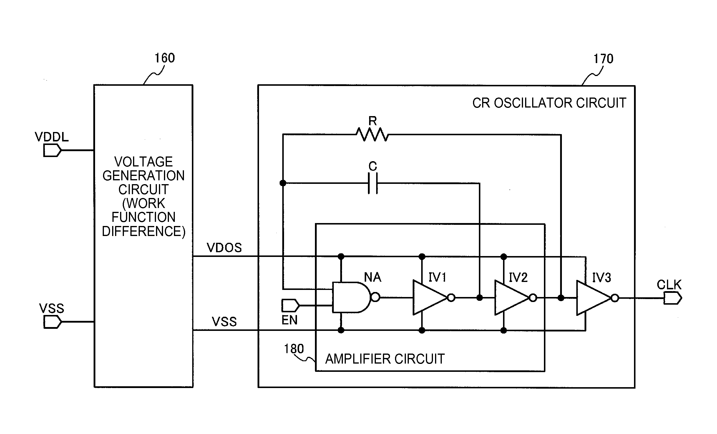
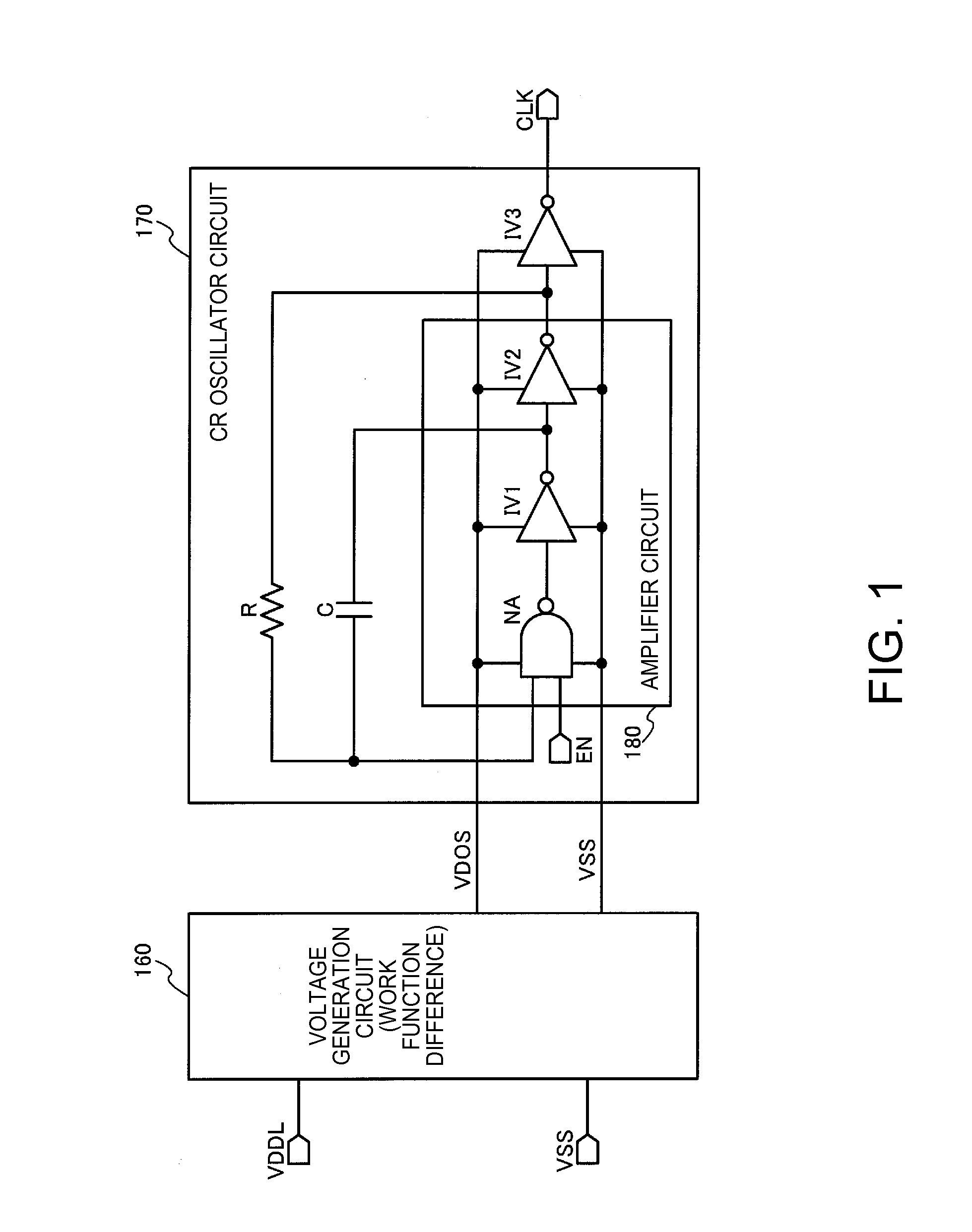
[0066]FIG. 1 shows a configuration example of a clock signal generation circuit according to the present embodiment. The clock signal generation circuit includes a voltage generation circuit 160 and a CR oscillator circuit 170. It should be noted that the clock signal generation circuit is not limited to the configuration shown in FIG. 1, but various practical modifications such as elimination of some of the constituents or addition of other constituents are possible.

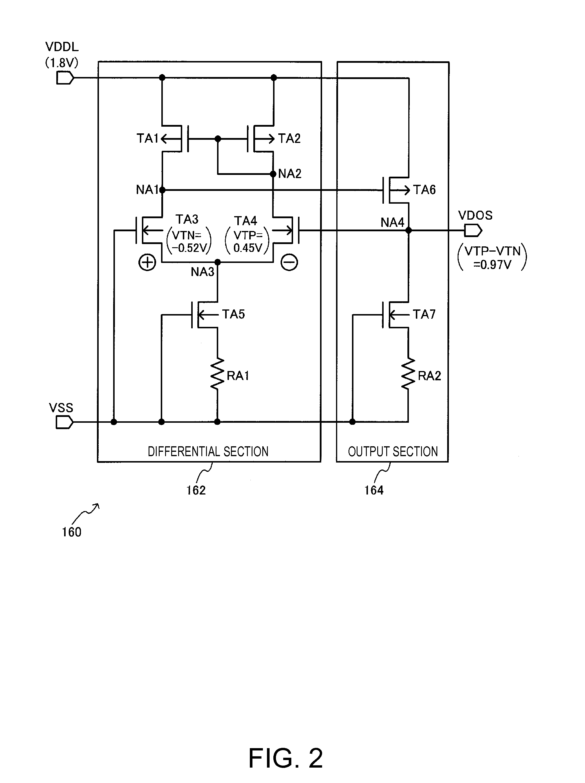
[0067]The voltage generation circuit 160 generates a power supply voltage VDOS, and then supplies the C...


PUM


Abstract

A clock signal generation circuit includes a CR oscillator circuit having a capacitor, a resistor, and an amplifier circuit, and a voltage generation circuit adapted to generate a power supply voltage, and then supply the CR oscillator circuit 170 with the power supply voltage VDOS. An oscillation frequency of the CR oscillator circuit in a case in which a power supply voltage VDDL is a fixed voltage has a positive temperature characteristic. The voltage generation circuit generates the power supply voltage VDOS having a negative temperature characteristic based on a work function difference between transistors, and then supplies the power supply voltage VDOS as a power of the amplifier circuit of the CR oscillator circuit.

Description

BACKGROUND[0001]1. Technical Field[0002]The present invention relates to a clock generation circuit, a detection device, a sensor, an electronic apparatus, and a moving object.[0003]2. Related Art[0004]In the past, there has been known a clock generation circuit using an oscillator circuit. In such an oscillator circuit, there is performed a temperature compensation for reducing the fluctuation of the oscillation frequency with respect to a temperature variation. As the related art of the temperature compensation of the oscillator circuit, there have been known technologies disclosed in JP-A-6-169237 (Document 1) and JP-A-2002-33644 (Document 2).[0005]In the related art of Document 1, for example, the temperature compensation of the oscillation frequency is realized by supplying a ring oscillator circuit having a negative temperature characteristic with a bias current having a positive temperature characteristic.[0006]In the related art of Document 2, the temperature compensation of...

Claims


Application Information

Patent Timeline
Patent Type & Authority Applications(United States)
IPC IPC(8): H03B5/04H03B5/24
CPCH03B5/24H03B5/04H03K3/011H03K3/03
Inventor HIGUCHI, TEPPEITANAKA, MASAFUMIMAKI, KATSUHIKO
Owner SEIKO EPSON CORP
Why Eureka
Try Eureka