Fuel cell module

a fuel cell and module technology, applied in the direction of electrochemical generators, chemistry apparatuses and processes, sustainable manufacturing/processing, etc., can solve the problems of inability inability to efficiently perform heat exchange, and large pressure loss, so as to improve the heat exchange efficiency and reduce the cost. , the effect of small heat demand

Active Publication Date: 2015-05-28
HONDA MOTOR CO LTD
View PDF3 Cites 3 Cited by
  • Summary
  • Abstract
  • Description
  • Claims
  • Application Information

AI Technical Summary

Benefits of technology

[0015]In the present invention, the exhaust gas combustor and the start-up combustor are provided in the first area at the center. The annular second area is provided around the first area, and the annular third area is provided around the second area, and the annular fourth area is provided around the third area, successively. In the structure, high temperature equipment with a large heat demand can be provided inside, and low temperature equipment with a small heat demand can be provided outside. Thus, improvement in the heat efficiency is achieved, and thermally self-sustaining operation is facilitated. Further, simple and compact struc...

Problems solved by technology

However, if the fins or the like are provided in the annular chamber, the pressure loss becomes large, and the heat exchange cannot be performed efficiently.
Further, in the conventional technique 3, i...

Method used


Image

  • Fuel cell module
  • Fuel cell module
  • Fuel cell module

Examples


first embodiment

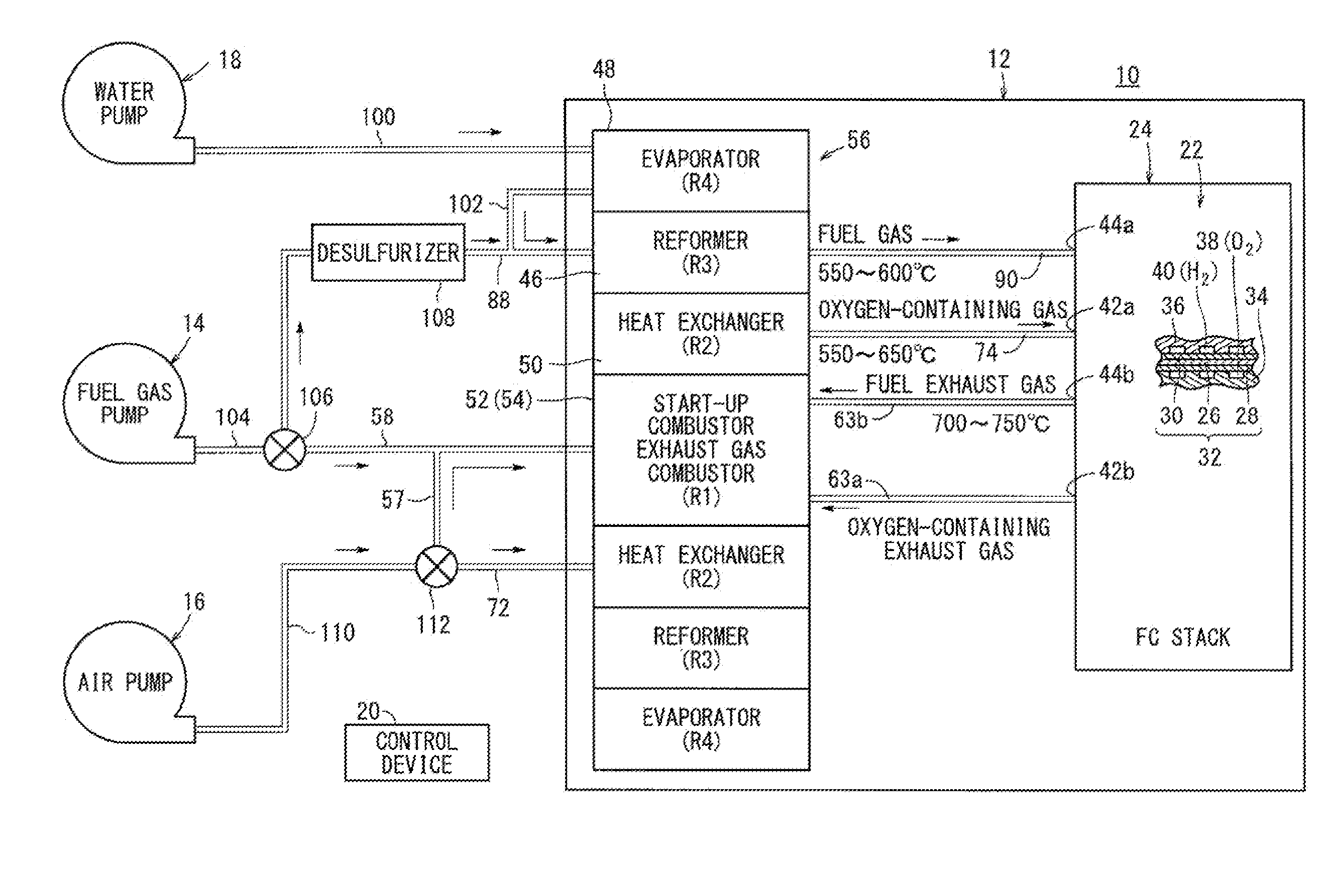
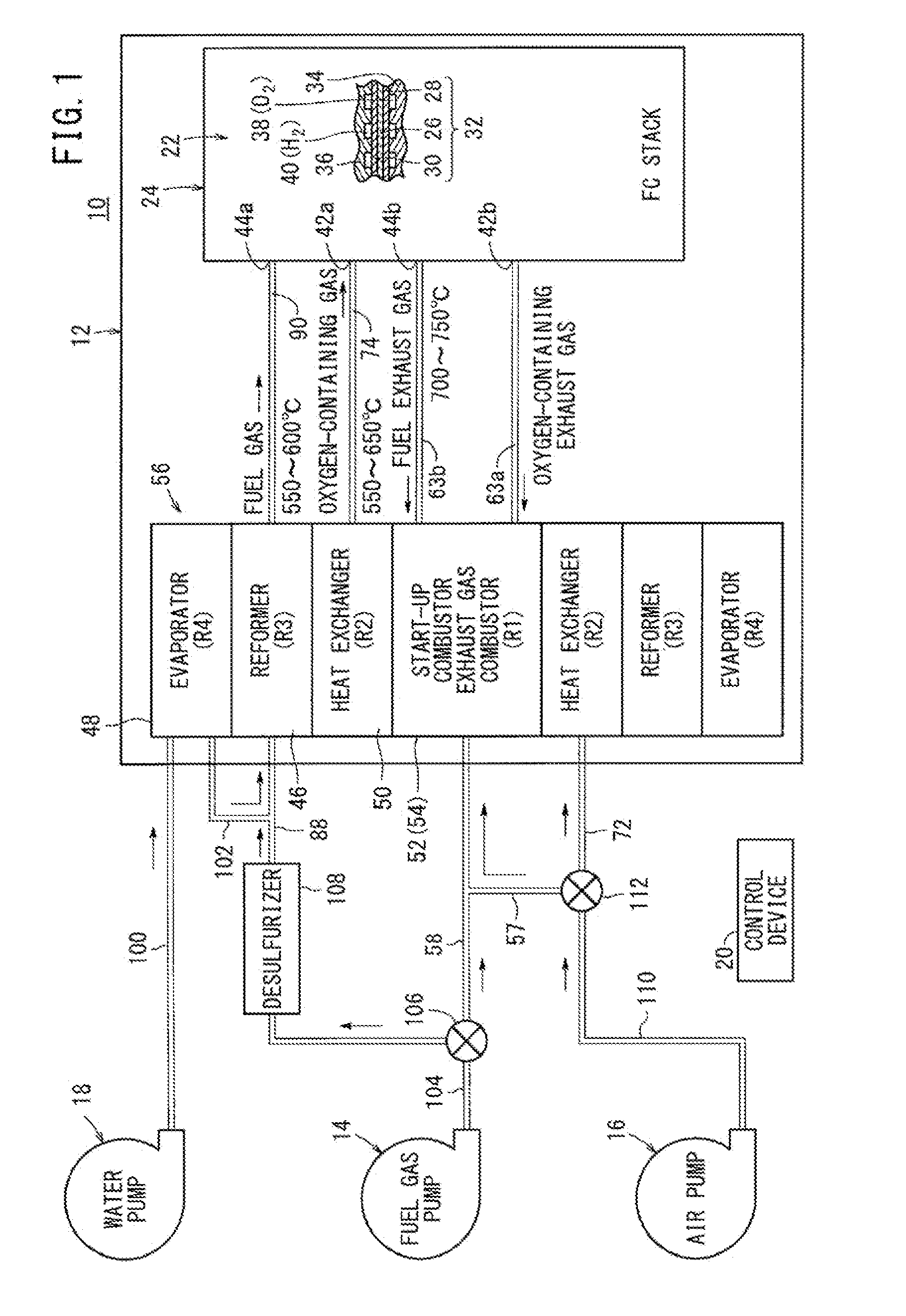
[0043]As shown in FIG. 1, a fuel cell system 10 includes a fuel cell module 12 according to the present invention, and the fuel cell system 10 is used in various applications, including stationary and mobile applications. For example, the fuel cell system 10 is mounted on a vehicle.

[0044]The fuel cell system 10 includes the fuel cell module (SOFC module) 12 for generating electrical energy in power generation by electrochemical reactions of a fuel gas (a gas produced by mixing a hydrogen gas, methane, and carbon monoxide) and an oxygen-containing gas (air), a raw fuel supply apparatus (including a fuel gas pump) 14 for supplying a raw fuel (e.g., city gas) to the fuel cell module 12, an oxygen-containing gas supply apparatus (including an air pump) 16 for supplying the oxygen-containing gas to the fuel cell module 12, a water supply apparatus (including a water pump) 18 for supplying water to the fuel cell module 12, and a control device 20 for controlling the amount of electrical e...

second embodiment

[0126]At least one, in the second embodiment, three baffle plates 122a, 122b, 122c forming a combustion gas detour channel are provided in the second area R2 (second combustion gas channel 116b) where the heat exchanger 50 is provided, between first inner rings 66a, 66b in a direction perpendicular to the pipe length direction of the heat exchange pipes 64. The baffle plates 122a to 122c have a substantially ring shape, and fixed to the outer circumferential surface of the first partition plate 60a and the inner circumferential surface of the second partition plate 60b, and have the same structure as the first inner ring 66a.

[0127]As shown in FIGS. 12 and 13, the baffle plates 122a to 122c have combustion gas flow holes 124 corresponding to the respective heat exchange pipes 64. Outer circumferential portions of the heat exchange pipes 64 are fitted to combustion gas flow holes 124 to position the heat exchange pipes 64, and openings are formed in the combustion gas flow holes 124 ...

third embodiment

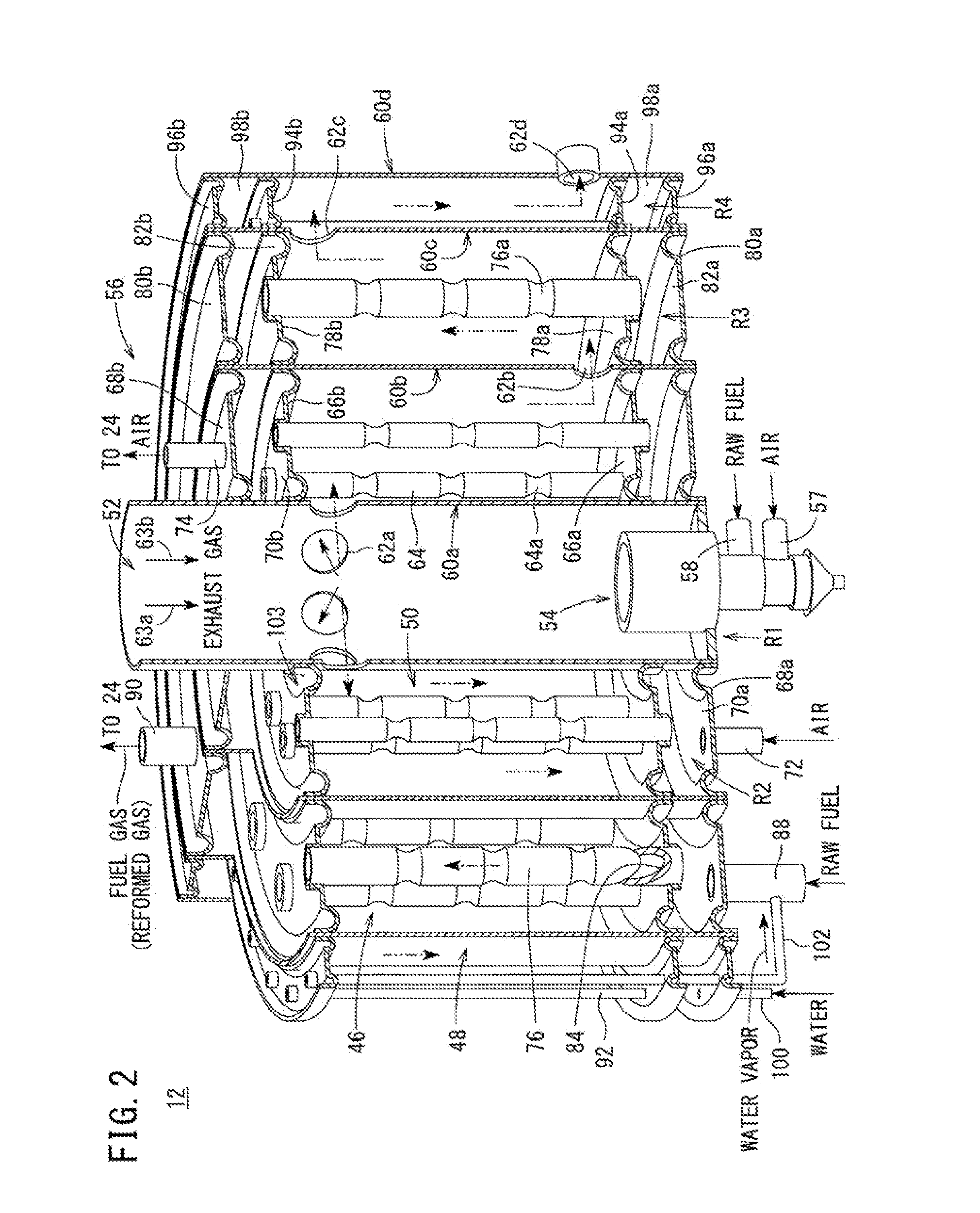
[0145]In the third embodiment, the fuel cell module 132 includes the first area R1 where the exhaust gas combustor 52 and the start-up combustor 54 are provided, the annular second area R2 around the first area R1 where the reformer 46 is provided, the annular third area R3 around the second area R2 where the heat exchanger 50 is provided, and the annular fourth area R4 around the third area R3 where the evaporator 48 is provided.

[0146]In the structure, high temperature equipment with a large heat demand such as the reformer 46 (and the heat exchanger 50) can be provided inside, and low temperature equipment with a small heat demand such as the evaporator 48 can be provided outside. Thus, improvement in the heat efficiency is achieved, and thermally self-sustaining operation is facilitated. Further, simple and compact structure is achieved.

[0147]Further, in the heat exchanger 50, transition from the laminar flow to the turbulent flow occurs in the oxygen-containing gas flowing throu...


PUM


Abstract

A fuel cell module includes a first area where an exhaust gas combustor and a start-up combustor are provided, an annular second area around the first area where a heat exchanger is provided, an annular third area around the second area where a reformer is provided, an annular fourth area around the third area where an evaporator is provided. A plurality of heat exchange pipes are provided in the heat exchanger around a first partition plate. At least one of the heat exchange pipes has at least one constricted portion.

Description

TECHNICAL FIELD[0001]The present invention relates to a fuel cell module including a fuel cell stack formed by stacking a plurality of fuel cells for generating electricity by electrochemical reactions of a fuel gas and an oxygen-containing gas.BACKGROUND ART[0002]Typically, a solid oxide fuel cell (SOFC) employs a solid electrolyte of ion-conductive oxide such as stabilized zirconia. The electrolyte is interposed between an anode and a cathode to form an electrolyte electrode assembly, for example, a membrane electrode assembly (hereinafter also referred to as MEA). The electrolyte electrode assembly is interposed between separators (bipolar plates). In use, generally, predetermined numbers of the electrolyte electrode assemblies and the separators are stacked together to form a fuel cell stack.[0003]As a system including this fuel cell stack, for example, a fuel cell battery disclosed in Japanese Laid-Open Patent Publication No. 2001-236980 (hereinafter referred to as conventional...

Claims


Application Information

Patent Timeline
IPC IPC(8): H01M8/06H01M8/24H01M8/04
CPCH01M8/0618H01M8/04268H01M2008/1293H01M8/24H01M8/04022H01M8/0631C01B3/384C01B2203/0233C01B2203/066C01B2203/0811C01B2203/1258C01B2203/1604H01M8/243H01M8/2483Y02E60/50Y02P20/10H01M8/2425
Inventor YOSHIMINE, YUKI
Owner HONDA MOTOR CO LTD
Why Eureka
Try Eureka