Method and device for detecting fluorescence radiation

a fluorescence radiation and detector technology, applied in the field of detectors for fluorescence radiation, can solve the problems of reducing no viable solution, and not addressing the problem of separating measured fluorescence radiation from background radiation, so as to achieve robust implementation, numerically reduce the effect of background radiation on measured signal, and improve the signal to noise ratio

Inactive Publication Date: 2015-05-28
QUEST PHOTONIC DEVICES
View PDF5 Cites 11 Cited by
  • Summary
  • Abstract
  • Description
  • Claims
  • Application Information

AI Technical Summary

Benefits of technology

[0014]By measuring at two different fluorescence wavelength ranges, and using knowledge of the fluorescence emission distribution curve at least in those ranges, the influence from the background radiation to the measured signal can be numerically reduced or practically eliminated. For example, based on the knowledge of the fluorescence curve, it is known what the ratio of the intensities at the two wavelength ranges should be in the absence of background radiation. In the presence of background radiation, which has an assumedly uniform intensity distribution at the two wavelengths, this ratio is modified. Using the knowledge of the unmodified ratio, it becomes possible to separate the contribution from the fluorescence radiation from the contribution from the background radiation. Thus, the signal to noise (fluorescence-to-background) ratio is advantageously improved. In addition, any following classification step of the measured fluorescence radiation may be improved, since the contribution of the background is removed or at least strongly diminished.
[0015]In an embodiment according the invention, the measurements at the at least two different fluorescence wavelength ranges are done simultaneously. A simultaneous rather than sequential measurement prevents problems with non-stationary samples. It can also allow for a more robust implementation as sequential measuring techniques often make use of moving parts (e.g. rotating mirrors or filter sets).
[0022]This way an image is obtained containing both visible details and the fluorescence radiation. The position of the fluorescence agent is thus easier to determine, and the fluorescence image will be easier to interpret.
[0032]The measurement device according the invention advantageously allows simultaneous measurements at both fluorescence radiation wavelengths. In addition, the design is more compact and robust than prior art systems comprising movable parts for sequential measurements.

Problems solved by technology

In addition, scattering of fluorescence photons in tissue further reduces the signal to noise ratio.
In real time systems during surgery however with varying light conditions this is no viable solution.
It does not address the problem of separating measured fluorescence radiation from background radiation.

Method used


Image

  • Method and device for detecting fluorescence radiation
  • Method and device for detecting fluorescence radiation
  • Method and device for detecting fluorescence radiation

Examples


Embodiment Construction

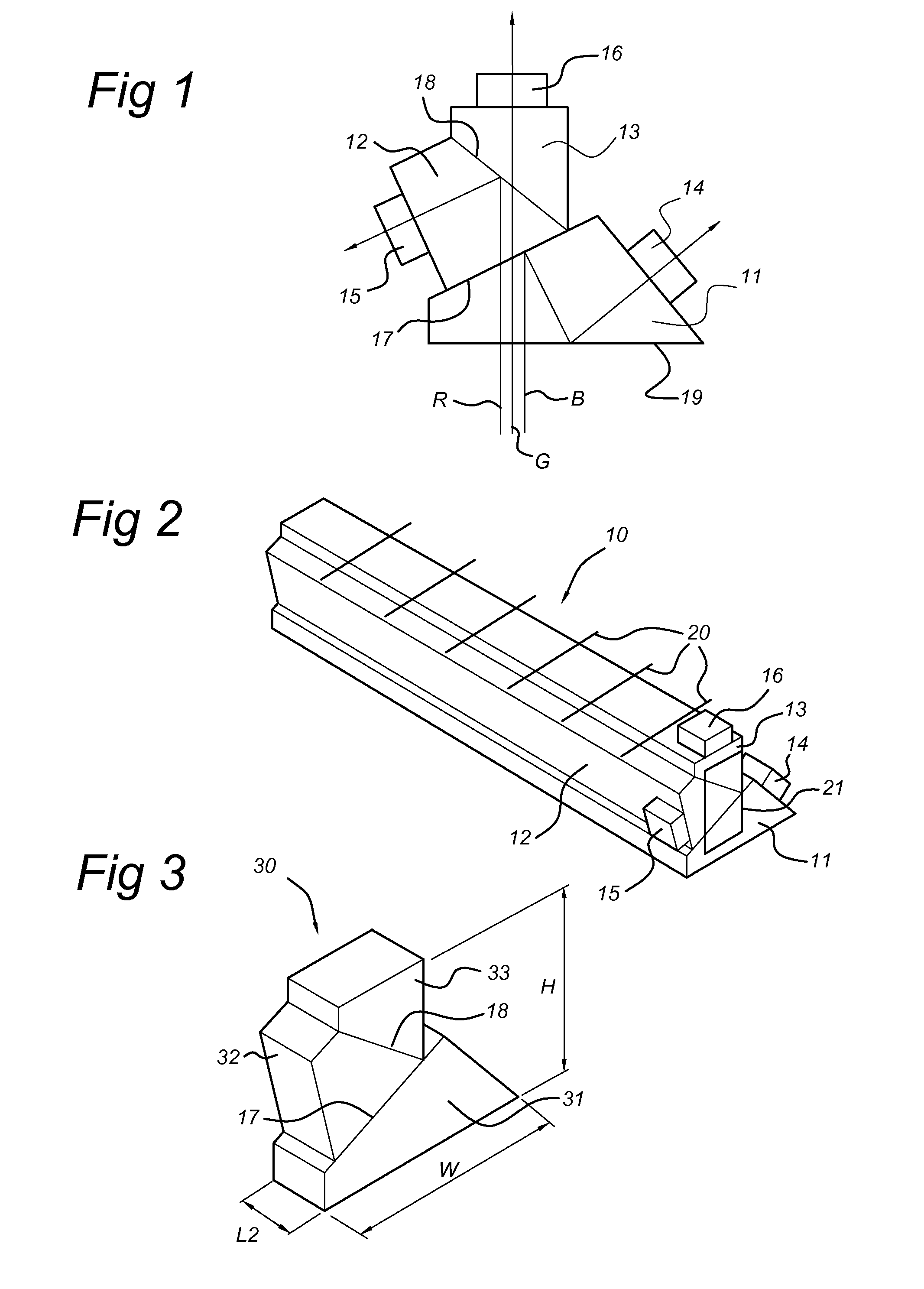
[0046]FIG. 1 schematically shows light paths through a dichroic prism assembly. An exemplary dichroic prism assembly configured to separate light into red R, green G, and blue B components will now be discussed to illustrate the functioning of such assembly. However, the invention is not limited to separation into R, G, and B. In reference to FIGS. 7-12, other wavelengths will be discussed. It will be clear to a skilled person that a dichroic prism assembly is a light separation means which can be configured to separate light into arbitrary wavelengths.

[0047]Returning to the exemplary assembly of FIG. 1, light comprising red R, green G and blue B components enters the assembly through incident surface 19, shown here as the bottom surface of the assembly. The first transition surface 17, between the first 11 and second prisms 12 comprises a coating that is configured to reflect blue light and transmit red and green light. The blue component B is nearly totally reflected and, due to t...


PUM

PropertyMeasurementUnit
wavelength rangeaaaaaaaaaa

Abstract

A method for detecting fluorescence radiation from a fluorescence agent, includes:emitting light at an excitation wavelength range (72) to cause fluorescence radiation emission in the fluorescence agent, the fluorescence radiation having a fluorescence wavelength profile (73);detecting light at a first fluorescence wavelength range (74) as a first detection signal (S1);detecting light at a second fluorescence wavelength range (81, 91) as a second detection signal (S2); andnumerically determining a third detection signal with an improved fluorescence-to-background radiation ratio based on the first detection signal (S1), the second detection signal (S2), and the fluorescence wavelength profile (73).

Description

FIELD OF THE INVENTION[0001]The invention relates to a method for detecting fluorescence radiation from a fluorescence agent using a probe such as an endoscope tip, to an endoscope tip suitable to perform said method, and to an endoscope system configured to perform said method. The invention also relates to an optical system comprising a camera and lens forming a probe other than an endoscope.BACKGROUND OF THE INVENTION[0002]In fluorescence imaging applications, a fluorescence dye or other fluorescence substance is applied as a labelling agent in an (internal) body part. With light at a specific wavelength (the excitation wavelength) from a light source such as a laser or LED, the fluorescence agent is excited. As a result, fluorescence light at a secondary wavelength is emitted by the agent. This light is sampled by an imaging sensor, such as a CCD sensor, of a probe to obtain a fluorescence signal. Especially when the probe must detect the fluorescence light through skin and tiss...

Claims


Application Information

Patent Timeline
Patent Type & Authority Applications(United States)
IPC IPC(8): A61B5/00A61B1/00A61K49/00G01N21/64A61B1/04
CPCA61B5/0071G01N21/6456A61B5/0084A61B5/7425A61B2576/02A61K49/0017A61B1/00193G01N2201/08A61B1/043A61B1/00009A61B1/00096A61B1/00186A61B1/051A61B1/0638F04C2270/0421
Inventor MEESTER, RICHARD JOHANNES CORNELIS
Owner QUEST PHOTONIC DEVICES
Why Eureka
Try Eureka