Organic molecules for oleds and other optoelectronic devices

a technology of organic molecules and optoelectronic devices, which is applied in the manufacture of non-metal conductors, conductors, and final products. it can solve the problems of complexes that are often more chemically reactive, insufficient long-term stability of these emitter materials, and high price of noble metals

Active Publication Date: 2015-06-04
SAMSUNG DISPLAY CO LTD
View PDF8 Cites 7 Cited by
  • Summary
  • Abstract
  • Description
  • Claims
  • Application Information

AI Technical Summary

Benefits of technology

[0003]Compared to conventional technologies, for instance liquid-crystal displays (LCDs), plasma displays or cathode ray tubes (CRTs), OLEDs have numerous advantages, such as a low operating voltage of a few volts, a thin structure of only a few hundred nm, high-efficiency self-illuminating pixels, high contrast and good resolution, and the possibility of representing all colors. In addition, in an OLED, light is produced directly on application of electrical voltage, rather than merely being modulated.
[0009]The phosphorescent organometallic triplet emitters known to date in OLEDs, however, have a disadvantage, which is that these complexes are frequently more chemically reactive in electronically excited states than in the base states. Responsible for this are generally metal-ligand bond breakages. Therefore, the long-term stability of these emitter materials is inadequate in many cases. (T. Sajoto, P. I. Djurovich, A. B. Tamayo, J. Oxgaard, W. A. Goddard III, M. E. Thompson; J. Am. Chem. Soc. 2009, 131, 9813). As a result, efforts are being made to develop emitter molecules without metal centers and with high emission quantum yield, wherein the emitter molecules shall furthermore also convert all singlet and triplet excitons into light. OLEDs using such emitters should exhibit a high efficiency, and additionally enable a longer lifetime of the optoelectronic device.

Problems solved by technology

This predominantly involves very expensive noble metals such as iridium, platinum or else gold.
The phosphorescent organometallic triplet emitters known to date in OLEDs, however, have a disadvantage, which is that these complexes are frequently more chemically reactive in electronically excited states than in the base states.
Therefore, the long-term stability of these emitter materials is inadequate in many cases.
In summary, the prior art can be described such that the triplet emitters which are efficient per se and are known to date have the disadvantages thatexpensive noble metal molecules have to be used and thatthese emitters formed on the basis of organometallic complexes have only inadequate long-term stability in many cases.

Method used


Image

  • Organic molecules for oleds and other optoelectronic devices
  • Organic molecules for oleds and other optoelectronic devices
  • Organic molecules for oleds and other optoelectronic devices

Examples


examples

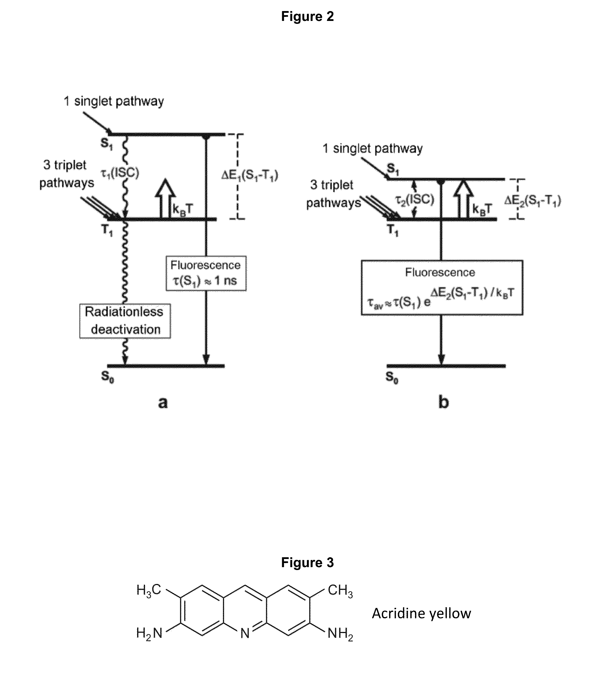
[0080]From the multitude of realizable organic molecules having a small singlet S1-triplet T1 energy difference, using the example of the emitters of formulas I to III, some examples are given, these having the following properties:[0081]The materials are very good emitters.[0082]The absorption and fluorescence transitions between the S0 and S1 states are allowed. Thus, the emission decay times τ(S1) are short.[0083]The examples include molecules having emissions from a broad spectral range.

[0084]An example of an organic molecule is defined by formula IV.

[0085]Herein, R1 to R9 are ═H, Br, I and / or groups, which are summarized in the examples for the donators D and / or acceptors A mentioned above. Adjacent Ri, Rj and Rk from R1 to R9 can be conjugated aromatic or heteroaromatic rings. Preferably Br and / or I also cause an increase of the spin orbit coupling.

[0086]R′ is either not present or H, Alkyl, O, S.

[0087]A further example for an organic molecule according to the invention is def...


PUM

PropertyMeasurementUnit
intersystem crossing time constantaaaaaaaaaa
emission decay timeaaaaaaaaaa
intersystem crossing time constantaaaaaaaaaa

Abstract

The invention relates to a composition having an organic emitter molecule, which has a ΔE(S1−T1) value between the lowest excited singlet state (S1) and the triplet state thereunder of less than 3000 cm−1 and an atom or molecule for reducing the intersystem crossing time constant of the organic molecule.

Description

[0001]The present invention relates to the use of specific organic dyes without metal centers as emitters in OLEDs (organic light-emitting diodes) and in other optoelectronic devices.INTRODUCTION[0002]Currently, it is apparent that OLED assemblies are already now of economic significance, since mass production is expected shortly. Such OLEDs consist predominantly of organic layers which can also be manufactured flexibly and inexpensively. OLED components can be configured with large areas as illumination bodies, but also in small form as pixels for displays.[0003]Compared to conventional technologies, for instance liquid-crystal displays (LCDs), plasma displays or cathode ray tubes (CRTs), OLEDs have numerous advantages, such as a low operating voltage of a few volts, a thin structure of only a few hundred nm, high-efficiency self-illuminating pixels, high contrast and good resolution, and the possibility of representing all colors. In addition, in an OLED, light is produced directl...

Claims


Application Information

Patent Timeline
Patent Type & Authority Applications(United States)
IPC IPC(8): H01L51/00C09K11/06
CPCH01L51/0072H01L51/006H01L51/0058H01L51/0071C09K11/06C09K2211/1096H01L51/5016C09K2211/1029C09K2211/1033C09K2211/1011H01L51/5028H10K85/6572H10K50/12Y02P70/50H10K85/626H10K85/633H10K50/11H10K2101/10C07D307/78C07D471/04C07F13/00H05B33/14H10K50/80Y02E10/549H10K85/657H10K50/121
Inventor YERSIN, HARTMUTHUPFER, ALEXANDER
Owner SAMSUNG DISPLAY CO LTD
Why Eureka
Try Eureka