
Heat dissipation structure

Active Publication Date: 2015-06-11
KANEKA CORP
View PDF1 Cites 23 Cited by
  • Summary
  • Abstract
  • Description
  • Claims
  • Application Information

AI Technical Summary

Benefits of technology

The present invention provides a thermally conductive curable resin composition that can fill the inside of an electromagnetic shielding case and reduce heat generated from electronic components. The resin composition can transfer heat from the electronic components to the shielding case and substrate, which helps to prevent deterioration in the electronic components. This heat dissipation structure is useful for protecting electronic components from overheating.

Problems solved by technology

If the above structure is used, however, the electronic components are then hermetically closed and thus have problems such as that the electronic components are likely to undergo an increase in temperature and degradation, or are less likely to exert their properties, compared to other components, because these electronic components are covered by air which is a poor conductor of heat, although electromagnetic shielding properties are not adversely affected.
However, since the thermally conductive resins disclosed are silicone resins, there is a concern regarding contact failures in electronic components due to volatilization of low molecular siloxane components or cyclic siloxane components.
Yet, unfortunately, the former material may leak from the system because it does not cure by nature; the latter material is not suited to fine bumps on electronic components.
Thus, these materials are inadequate as countermeasures against heat from electronic components in such an electromagnetic shielding case described above.
However, personal digital assistants such as smartphones and tablets cannot be provided with sufficient space for heat dissipation.
Without efficient heat dissipation, their electronic components can have the problem that they will readily undergo an increase in temperature and degradation, for example.
In addition, since it cures at room temperature, leakage of the thermally conductive material from the system over time, which is a problem associated with grease-like thermally conductive materials, will not occur, and volatilization of low molecular siloxane components or cyclic siloxane components, which is a problem associated with silicone-based thermally conductive materials and causes contact failures in heat-generating electronic components, cannot occur.
However, since a silicone composition is used, the above-described problem of volatilization of low molecular siloxane components still exists.

Method used


Image

  • Heat dissipation structure
  • Heat dissipation structure
  • Heat dissipation structure

Examples


examples

[0088]Embodiments and effects of the present invention are described below by reference to examples, but the present invention is not limited to these examples.

(Synthesis 1)

[0089]In a nitrogen atmosphere, a 250-L reactor was charged with CuBr (1.09 kg), acetonitrile (11.4 kg), butyl acrylate (26.0 kg), and diethyl 2,5-dibromoadipate (2.28 kg), and the mixture was stirred at 70° C. to 80° C. for about 30 minutes. Then pentamethyldiethylenetriamine was added to the mixture and a reaction was started. After 30 minutes from the start of the reaction, butyl acrylate (104 kg) was continuously added to the mixture over two hours. During the reaction, pentamethyldiethylenetriamine was added as needed so that the internal temperature was maintained at 70° C. to 90° C. The total amount of pentamethyldiethylenetriamine used up to this point was 220 g. After four hours from the start of the reaction, the mixture was heated while stirring under reduced pressure at 80° C. to remove volatile matte...

examples 5 and 6

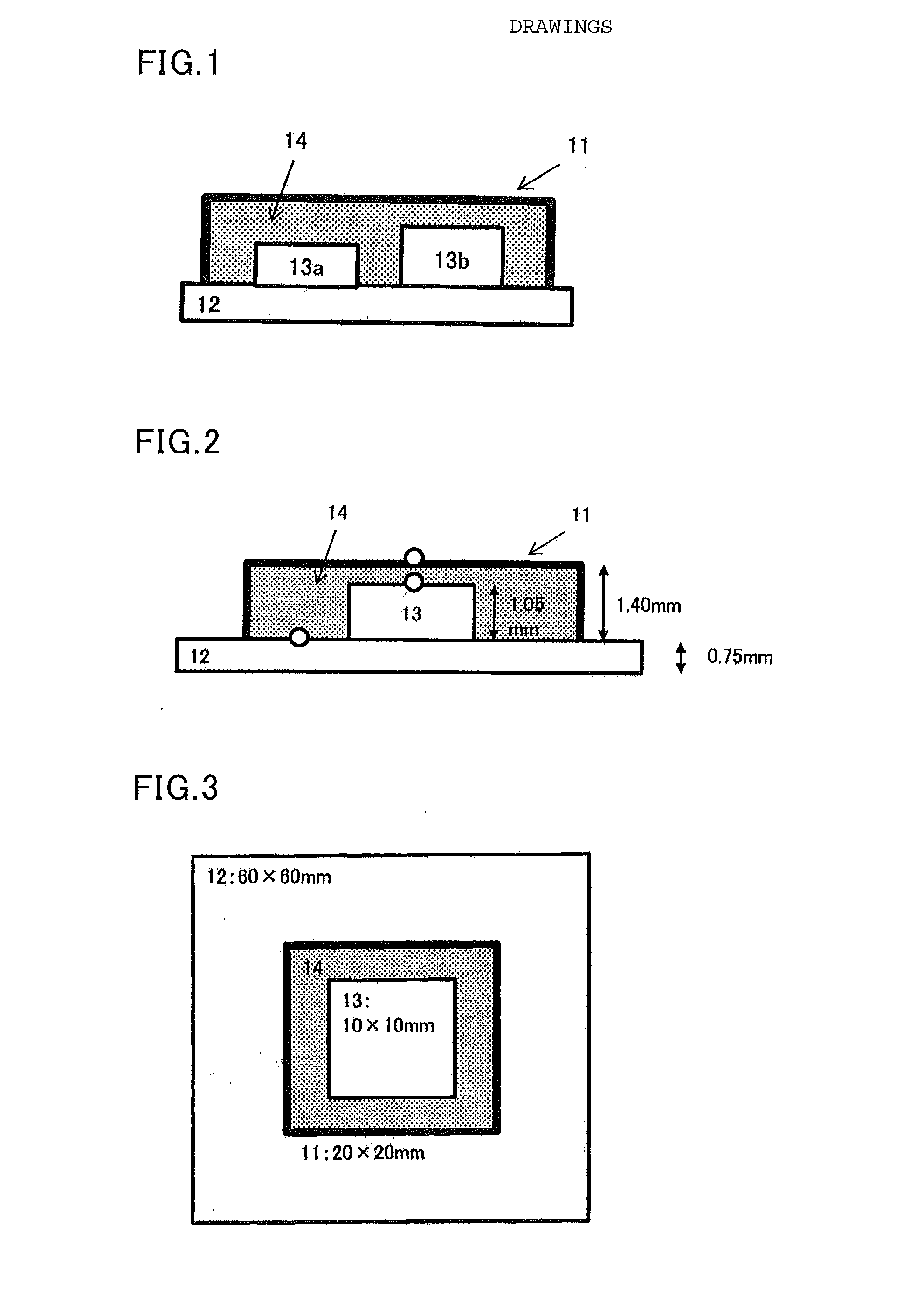
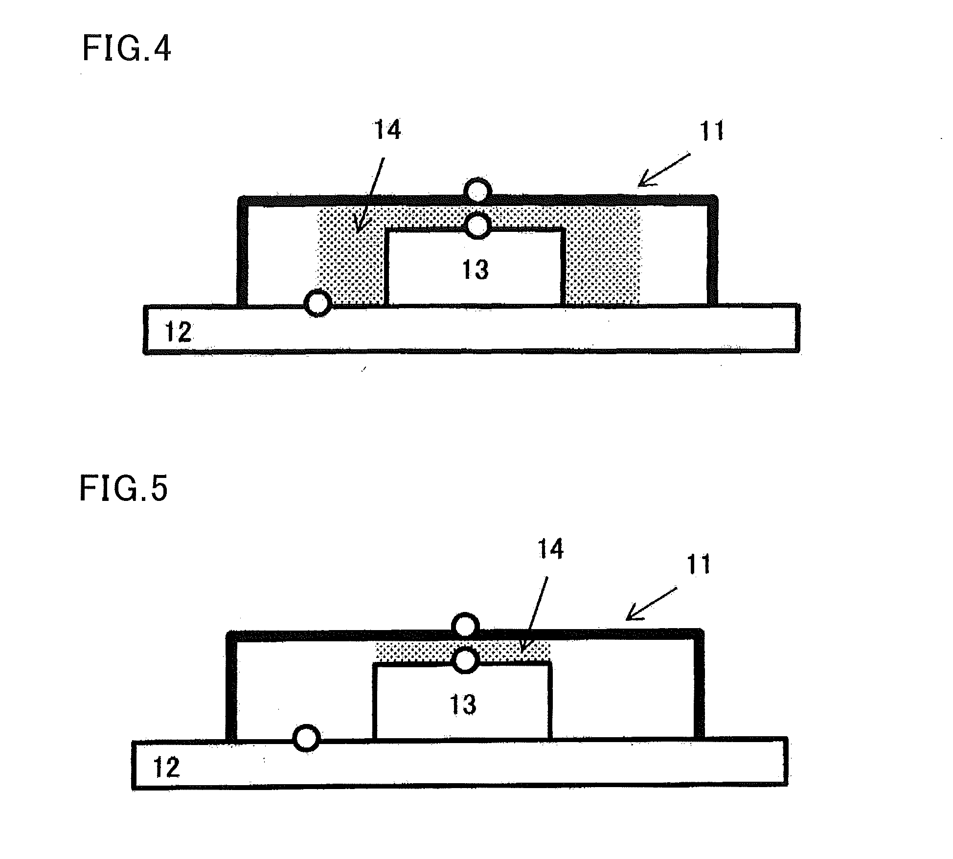
[0098]The resin (I-1) obtained in Synthesis 1 (90 parts by weight), the resin (I-2) obtained in Synthesis 2 (10 parts by weight), a plasticizer (Monocizer W-7010 available from DIC; 100 parts by weight), an antioxidant (Irganox 1010; 1 part by weight), and thermally conductive fillers shown in Table 2 were sufficiently stirred and kneaded with hands. Then the mixture was dehydrated under vacuum while kneading under heat using a 5-L butterfly mixer. After the completion of dehydration, the mixture was cooled and mixed with a dehydrating agent (A171; 2 parts by weight) and curing catalysts (tin neodecanoate and neodecanoic acid; 4 parts by weight each). Thus, a thermally conductive curable resin composition was obtained. After the obtained thermally conductive curable resin composition was measured for viscosity and thermal conductivity, the thermally conductive curable resin composition was filled in simple models as shown in FIGS. 4 and 5, and the temperature and the presence or abs...

example 7

[0106]The resin (I-1) obtained in Synthesis 1 (100 parts by weight), a plasticizer (DIDP available from J-PLUS Co., Ltd.; 100 parts by weight), an antioxidant (Irganox 1010 available from Ciba Japan K.K.; 1 part by weight), and thermally conductive fillers (AS-40 (alumina available from Showa Denko K.K.) / zinc oxide (available from Sakai Chemical Industry Co., Ltd)=1070 / 500 (parts by weight)) were sufficiently stirred and kneaded with hands. Then the mixture was dehydrated under vacuum while kneading under heat using a 5-L butterfly mixer. After the completion of dehydration, the mixture was cooled and mixed with a dehydrating agent (A171 available from Dow Corning Toray Co., Ltd.; 4 parts by weight) and a curing catalyst (tin neodecanoate U-50H available from NITTO KASEI KOGYO K.K.; 4 parts by weight). Thus, a thermally conductive curable resin composition was obtained. Table 3 shows the evaluation results.


PUM

PropertyMeasurementUnit
Temperatureaaaaaaaaaa
Poweraaaaaaaaaa
Energyaaaaaaaaaa

Abstract

The present invention provides a heat dissipation structure that does not cause problems such as contact failures in electronic components and that is applicable to electronic components with high heat densities. The present invention also provides a method for easily repairing an electronic device. The heat dissipation structure is obtained by filling and curing a thermally conductive curable resin composition in an electromagnetic shielding case on a substrate on which an electronic component with a heat density of 0.2 W / cm2 to 500 W / cm2 is mounted, the thermally conductive curable resin composition containing a curable liquid resin (I) and a thermally conductive filler (II), having a viscosity at 23° C. of 30 Pa·s to 3000 Pa·s and a thermal conductivity of 0.5 W / (m·K) or more, and being curable by moisture or heat.

Description

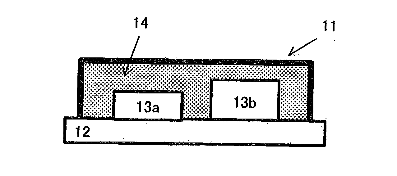
TECHNICAL FIELD[0001]The present invention relates to a heat dissipation structure obtained by filling and curing a thermally conductive curable resin composition in an electromagnetic shielding case on a substrate for use in electronic devices, precision apparatus, or the like.BACKGROUND ART[0002]To prevent superimposition of external electromagnetic waves as noise on input and output signals to and from electronic components (components that generate heat while electronic devices are being operated) as well as superimposition of electromagnetic waves generated from the electronic components themselves as noise on other signals, it has conventionally been proposed to shield electromagnetic waves entering and leaving the electronic components. Electromagnetic shielding cases that are configured to cover from above one or multiple electronic components mounted on a printed circuit board with a metal case are known.[0003]If the above structure is used, however, the electronic componen...

Claims


Application Information

Patent Timeline
IPC IPC(8): H05K7/20C08L71/02B29C73/02C08L33/00
CPCH05K7/2039B29C73/02C08L71/02C08L33/00H05K7/20463H05K9/0024H01L23/3121H01L23/3737H01L23/552H01L25/0655H01L2924/0002H01L23/42H01L2924/16151H01L2924/16251H01L23/295H01L2924/166H01L2924/3025H01L2924/00H05K9/0032
Inventor OGUMA, KEISUKEKOUKAMI, AKIHAGIWARA, KAZUO
Owner KANEKA CORP
Learn More