Cooling structure for urea aqueous solution conduit

a technology cooling structure, which is applied in the direction of machine/engine, lighting and heating apparatus, separation processes, etc., can solve the problems of urea aqueous solution deterioration

Active Publication Date: 2015-06-25
KOMATSU LTD
View PDF4 Cites 19 Cited by
  • Summary
  • Abstract
  • Description
  • Claims
  • Application Information

AI Technical Summary

Benefits of technology

[0017]According to the fourth aspect of the invention, outer air can reliably flow into the pipeline-forming member through the air intake hole provided on the exterior cover. In this arrangement, the outside (an outside of the engine compartment) and the pipeline-forming member intercommunicate with each other through the air intake hole. In other words, since the inside and the outside of the engine compartment do not intercommunicate with each other through the air intake hole, there is no fear of increasing noise.
[0018]According to the fifth aspect of the invention, the portion of the exterior cover under which the pipeline-forming member is provided is openable and closeable and the pipeline-forming member is attached to a portion of the exterior cover other than the portion under which the pipeline-forming member is provided. Accordingly, even when the above portion of the exterior cover is opened, the urea aqueous solution pipe is not drawn out of the engine compartment together with the pipeline-forming member, so that maintenance of the pipeline-forming member left in the engine compartment and the urea aqueous solution pipe laid in the pipeline-forming member can be easily performed.

Problems solved by technology

Since such a urea aqueous solution pipe is installed in an engine compartment, the urea aqueous solution may be deteriorated by thermal influence from the engine.

Method used


Image

  • Cooling structure for urea aqueous solution conduit
  • Cooling structure for urea aqueous solution conduit
  • Cooling structure for urea aqueous solution conduit

Examples


Embodiment Construction

)

[0025]An exemplary embodiment of the invention will be described below with reference to the drawings.

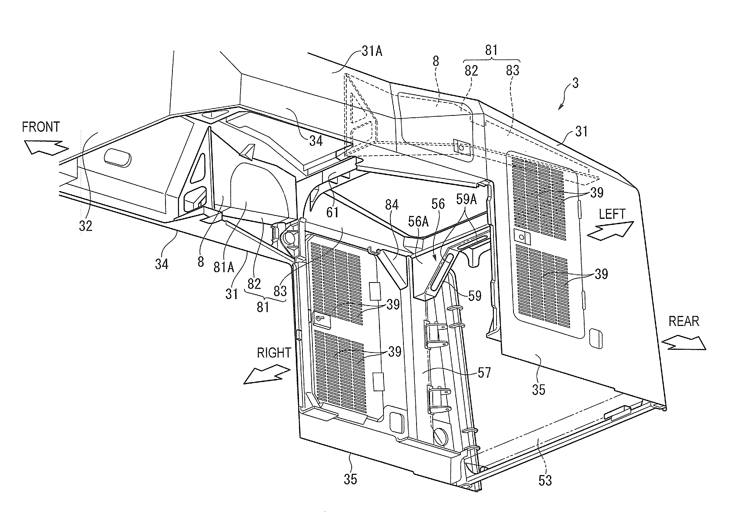
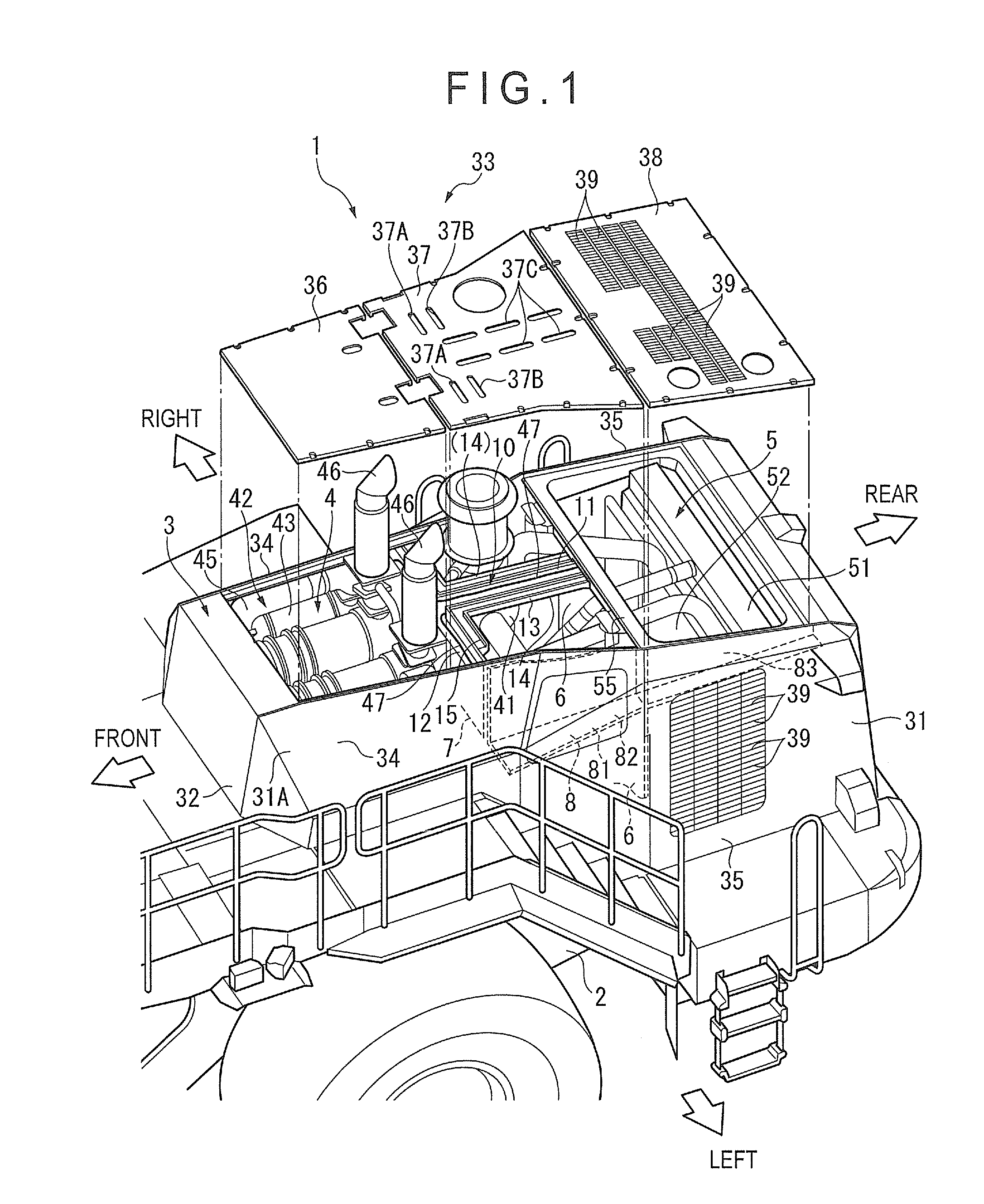
[0026]FIG. 1 is an exploded perspective view showing a part of a working vehicle 1 provided with a cooling structure of an engine compartment 4 according to the exemplary embodiment of the invention.

Description of Overall Vehicle

[0027]In FIG. 1, the working vehicle 1 is in a form of a wheel loader including a front frame (not shown) and a rear frame 2 connected to the front frame in a manner capable of being articulated. Working equipment that includes a boom, a bell crank, a bucket and hydraulic actuators that actuate the boom, bell crank and the bucket is provided on the front frame of the working vehicle 1. It should be noted that an illustration and a description of the working equipment are omitted since the working equipment is not directly relevant to the invention.

[0028]On the rear frame 2 of the working vehicle 1 and behind a cab (not shown), the engine compartment 4 and a...


PUM

PropertyMeasurementUnit
cooling structureaaaaaaaaaa
structureaaaaaaaaaa
temperatureaaaaaaaaaa

Abstract

In a working vehicle, an exhaust gas aftertreatment device is provided in an engine compartment that is adjacent to a cooling fan through which cooling air is supplied to a heat exchanger. The exhaust gas aftertreatment device includes a selective catalytic reduction device in which ammonia obtained from a urea aqueous solution is used as a reduction-causing agent. A urea aqueous solution pipe through which the urea aqueous solution is supplied is laid to the selective catalytic reduction device through the engine compartment. In the engine compartment, a pipeline-forming member having pipelines in which the urea aqueous solution pipe is installed. The cooling air sucked by a cooling fan flows into the pipelines.

Description

TECHNICAL FIELD[0001]The present invention relates to improvement in a cooling structure of a urea aqueous solution pipe.BACKGROUND ART[0002]It has been known that particulate matters (PM) contained in exhaust gas discharged from an internal combustion engine (e.g., a diesel engine) are collected by a dedicated filter (i.e., Diesel Particulate Filter (DPF)). Since the regulation for the exhaust gas has become stricter recently, further purification of the exhaust gas is desired. Accordingly, an exhaust gas aftertreatment device desirably includes a reduction-causing catalyst that purifies nitrogen oxides in the exhaust gas in addition to the DPF.[0003]A reduction-causing agent in a form of ammonia obtained from a urea aqueous solution is used for such a reduction-causing catalyst Ammonia in a state of a urea aqueous solution is pumped from a tank to an injector and injected from the injector into an exhaust pile (a mixing pipe) on an upstream of the reduction-causing catalyst. The i...

Claims


Application Information

Patent Timeline
Patent Type & Authority Applications(United States)
IPC IPC(8): F01N3/05F01N3/20F01N3/02
CPCF01N3/05F01N3/2066F01N3/0205B01D53/90B01D53/9431B01D2251/2067F01N2610/02E02F9/0866F01N2260/022F01N2590/08F01N2610/11F01N2610/14E02F9/0858F01P1/06F01N13/143Y02A50/20Y02T10/12F01N3/055F01N13/001F28D9/0043F01N2470/08B01D53/86B01D53/94F01P11/10F01P2001/005
Inventor TSUTSUMI, KATSUHIROMIYAMOTO, HIROFUMI
Owner KOMATSU LTD
Why Eureka
Try Eureka