
Vibration assisted vacuum dewatering of fine coal particles

Active Publication Date: 2015-07-02
EARTH TECH USA
View PDF14 Cites 20 Cited by
  • Summary
  • Abstract
  • Description
  • Claims
  • Application Information

AI Technical Summary

Benefits of technology

The invention is about a way to get rid of excess water from a flotation process that separates hydrophobic and hydrophilic minerals. The method is particularly useful for dewatering the hydrophobic particles in coal-froth.

Problems solved by technology

The current industrial process to recover coal particles less than 1 mm in size is more expensive than other coal processing.
The smaller the particles, the greater the processing cost.
Further, there are no current commercial processes to recover and sell particles less than 100 microns (0.1 mm).
While coal dust (fines) is the same composition of the other mined product, it is considered waste because the conventional coal recovery process is not designed to handle small particles.
The waste coal dust is left unused because it is typically too wet to burn, too dirty to be worth drying, and too fine to transport.
While coal fines separation, classification and drying technologies are known, they are too inefficient and expensive with particles less than 150 microns to be commercially feasible.
Further significant money is being wasted in the transportation and handling of the moisture fraction and the ash-forming mineral fraction of the coal.
Even with recent advances in some coal processes, including attempts to recover coal fines via coal flotation processes, the coal industry does not have an effective process for upgrading and handling coal fines less than 500 microns (0.5 mm), more specifically less than 300 microns (0.3 mm), less than 150 microns (0.15 mm), less than 100 microns (0.1 mm), and certainly less than 50 microns (0.05 mm).
These massive amounts of fine waste are an inefficiency caused by current coal industry practices and are an environmental and disposal problem.

Method used


Image

  • Vibration assisted vacuum dewatering of fine coal particles
  • Vibration assisted vacuum dewatering of fine coal particles
  • Vibration assisted vacuum dewatering of fine coal particles

Examples


example 1

General Comparison of Dewatering Processes

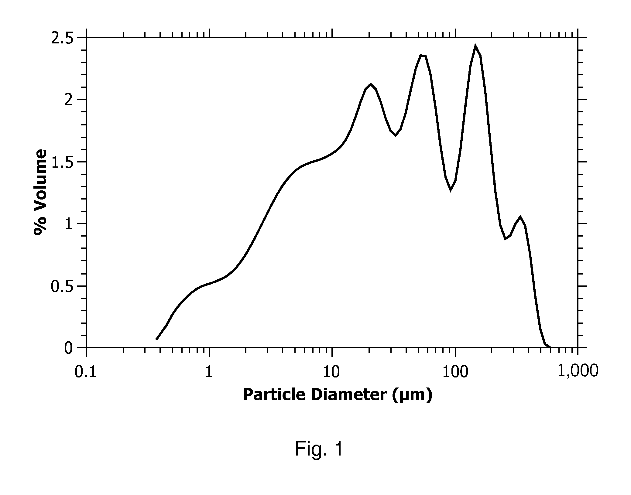
[0041]Laboratory tests show that the moisture content of the cake produced by mechanical dewatering techniques is dependent upon the particle size distribution. A gravity dewatering technique and different mechanical dewatering techniques were tested on coal-froth containing 95 wt. % coal particles on a dry basis with the particle size distribution shown in FIG. 1. The different dewatering techniques / equipment included a lab-scale thickener test, a pilot-scale screen-bowl centrifuge, a pilot-scale filter press, a pilot-scale vacuum dewatering drum, a vacuum ceramic disc filter, and a lab-scale tower press. The results are shown in Table 1.

TABLE 1Comparison of Dewatering TechniquesMoisture ContentMoisture content ofDewatering Techniqueof Froth (wt. %)dewatered cake (wt.)Thickener with flocculant75%52%(gravity)Pilot-scale screen-bowl55%31%centrifugePilot-scale filter press55%37%Pilot scale vacuum55%31%dewatering drumCeramic disc filter55%26% t...

example 2

Thixotropic Nature of the Filter Cake

[0046]When handling the cakes produced with the different mechanical dewatering techniques listed in Table 1 at moisture contents between 30 wt. % to 38 wt. %, it was observed that cakes tended to flow more readily when shearing force was added to the cake. Furthermore, when the cake was laid out on a table and patted by hand, moisture would migrate to and pool at the surface of the cake. Vibration was applied to the cake on the table and two things happened: the cake flowed readily to produce a thinner cake on the table and water migrated to the surface of the cake and pooled there. The described observation of shear thinning or becoming less viscous when a shear force or vibration force is applied is characteristic of a thixotropic material.

[0047]An experiment was done to understand two things: (1) the effect of vibration on vacuum dewatering and (2) the influence particle size has on the moisture content of the cake that was produced via vacuu...

example 3

Vibration Assisted Dewatering in a Pilot-Scale Buchner Funnel Vacuum Dewatering System

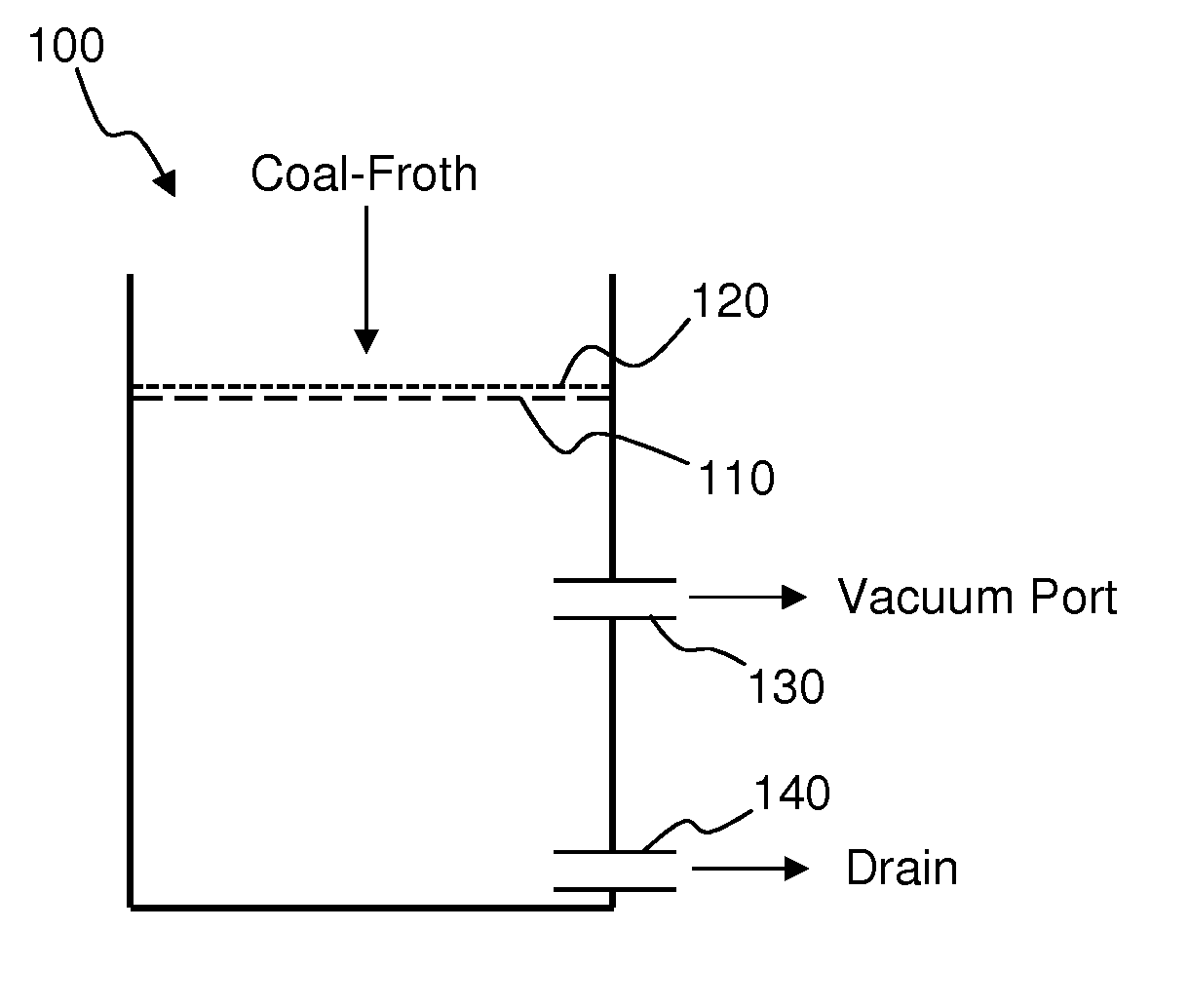
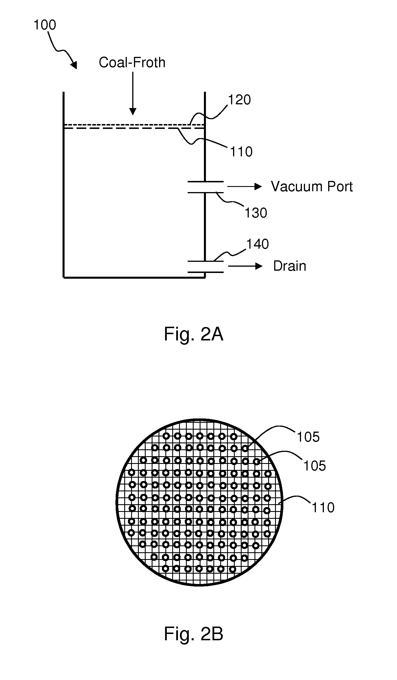
[0051]A pilot-scale Buchner funnel vacuum dewatering unit was made by modifying a 30 gallon stainless steel drum that is about 18 inches in diameter and 28 inches tall to process larger amounts of coal-froth. A schematic, cross-sectional representation of this pilot-scale Buchner funnel vacuum dewatering unit 100 is shown in FIG. 2A. One-half inch holes 105 were drilled into the lid 110 to support an overlying 55 μm mesh screen 120. FIG. 2B shows a schematic top view of the lid 110 with holes 105. A vacuum pump (Model SW-300-L manufactured by Shinko Seiki) was used to pull vacuum on the drum via a vacuum port 130. A drain 140 is provided to drain the water drawn through the screen 120 and holes 105. When just pumping air, this vacuum pulls more than 40 standard cubic feet per minute (SCFM) air through a 1 inch inside diameter tube. When coal-froth was poured onto the screen 120, a maximum vacuum of...


PUM


Abstract

Fine coal particles are dewatered by mechanically removing water from the coal particles by vibration assisted vacuum dewatering to form a coal particle filter cake. The filter cake typically has a water content less than 35% by weight, suitable for extrusion to form discrete, non-tacky pellets. The vibration assisted vacuum dewatering may operate at a vibration frequency in the range from about 1 Hz to about 500 Hz. The vibration frequency may be adjusted during the dewatering process. In some embodiments, the vibration frequency is increased as the moisture content of the coal particle filter cake is decreased. Washing the filter cake during dewatering removes soluble contaminants. Various vibration assisted vacuum dewatering devices may be used, including a vibration assisted rotary vacuum dewatering drum, a vibration assisted vacuum disk filter, and a vibration assisted vacuum conveyor system.

Description

CROSS-REFERENCE TO RELATED APPLICATIONS[0001]This application claims the benefit of U.S. Provisional Patent Application No. 61 / 922,374, filed Dec. 31, 2013, titled VIBRATION ASSISTED VACUUM DEWATERING OF COAL FINES and the benefit of U.S. Provisional Patent Application No. 61 / 985,721, filed Apr. 29, 2014, titled CAMSHAFT MECHANISM FOR APPLYING VIBRATION TO THE SURFACE OF FILTER CAKE, which applications are incorporated by reference.BACKGROUND OF THE INVENTION[0002]This disclosure relates to systems and methods for dewatering fine coal particles to form a filter cake. More specifically, the disclosed systems and methods include vibration assisted vacuum dewatering of fine coal particles.BACKGROUND[0003]Coal is one of the most important energy sources in the world. There are many grades of coal based on the ash content, moisture, macerals, fixed carbon, and volatile matter. Regardless of grade however, the energy content of coal is directly correlated to its moisture and ash-forming m...

Claims


Application Information

Patent Timeline
IPC IPC(8): C10L5/04C10L5/26C10L5/08
CPCC10L5/04C10L5/08C10L2290/08C10L2250/06C10L2230/14C10L5/26C10L5/363C10L2290/547
Inventor SWENSEN, JAMES S.HODSON, SIMON K.HODSON, JONATHAN K.
Owner EARTH TECH USA
Learn More