Solar receiver

a solar receiver and receiver technology, applied in the field of solar energy systems, can solve the problems of affecting the safety of solar heat collectors, affecting the performance of solar energy collectors, and requiring re-alignment, so as to enhance the precision of the formed surface, the effect of enhancing the precision

Inactive Publication Date: 2015-07-02
SHELEF BEN +1
View PDF14 Cites 8 Cited by
  • Summary
  • Abstract
  • Description
  • Claims
  • Application Information

AI Technical Summary

Benefits of technology

[0037]According to embodiments of the invention, the reflector structure and reflector panels work in concert to achieve several other advantages. The tiles attach to the primary structure from the back side, which allows them to be replaced without interference with the rest of the dish, without placing people inside the optical path, and without requiring subsequent re-alignment.
[0038]Additionally, according to embodiments of the invention, the primary structure determines the position of the front surface of the tiles which enhances the precision of the formed surface. The composite front surface created is continuous, and so allows for collection of the water used while washing

Problems solved by technology

The “truss and glass” dish architecture described above is performance limited due to several factors.
Typical truss-based primary mirror designs weigh around 50 kg/m2, and their assembly and alignment in the field is very time consuming, taking more than a day for the 100 m2 reflector described above.
The large part count introduces tolerance stack-up errors, and the large number of joints are all sources of stress concentration, fatigue, and structural creep.
If the structure creeps over time, alignment has to be re-done.
The heavy weight of the dish and in particular its large moment of inertia makes precise tracking difficult, and either increases the cost of the actuation machinery or reduced tracking accuracy, which results in reduced output.
In boom-based designs, the mass is distributed in a dumbbell-like way, which is the worst case in terms of rotational moment of inertia, which makes tracking more difficult.
Boom flexing adds another oscillation mode and further complicates alignment and tracking Stiffening the boom adds mass to the system.
The slice that has to be cut in the dish reduces the optical area, reduces its rigidity, and degrades optical accuracy.
The optical surface precision of the reflector tiles is also lacking in practice, due to the shell/glass structure having insufficient precision.
This problem can be solved with “brute force” precision optical processes such as glass grinding, but in solar power design, cost and fabrication speed are major design considerations, and those processes are prohibitive.
Finally, optical performance is hindered by accumulated dust and dirt on the optical

Method used


Image

  • Solar receiver
  • Solar receiver
  • Solar receiver

Examples


first embodiment

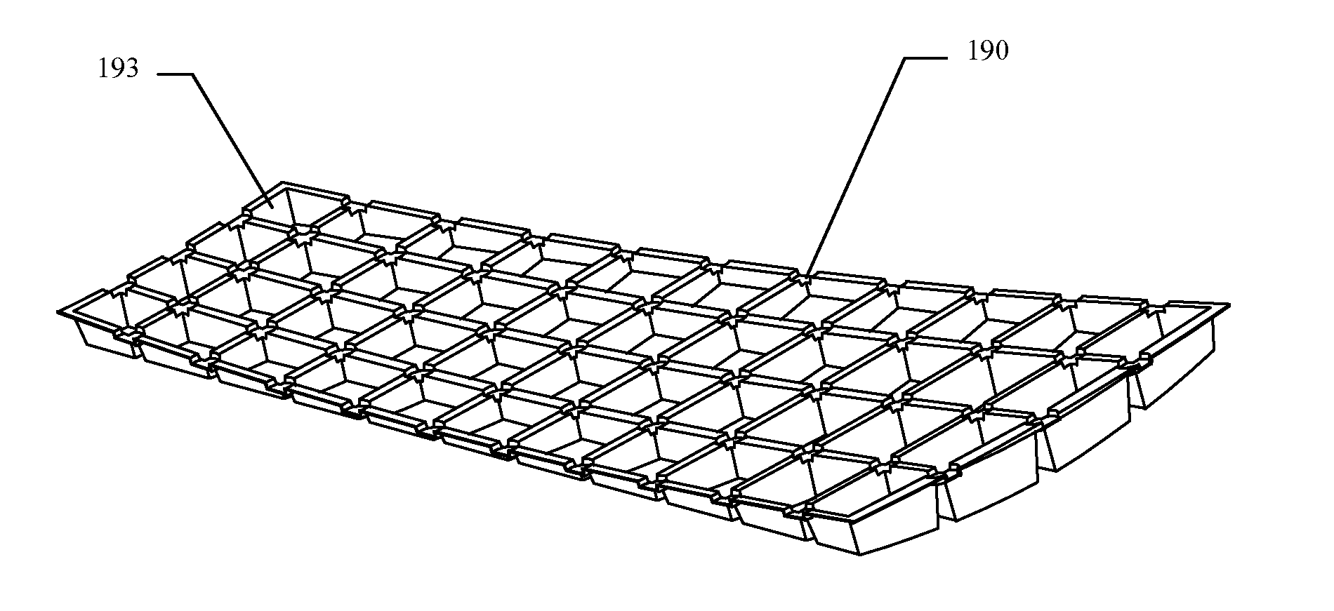
[0199]FIGS. 19a-c shows several embodiments of the core with different tile and cup geometries. In the first embodiment shown (FIG. 19a), the tile core is implemented with trapezoid or rectangular cups [193] instead of triangular one. The packing of the cups is more efficient than that of the triangles, and their fit to the side edges of the tile is more consistent and uniform. In this embodiment, reliefs [190] are formed to alleviate thermal expansion conflicts between the core material and the membrane material. The reliefs are formed by adding corresponding depressions to the vacuum mold.

[0200]The next embodiment shown (FIG. 19b, front, and FIG. 19c, back) is of a core for a rectangular almost-flat reflector panel (such as is used with Heliostats) which uses round cups [191], and additionally has sidewalls [192] formed during the vacuum forming process, helping in sealing the tile structure against dirt and moisture. In a slight variation, the circular cups can be replaced by hex...

second embodiment

[0290]As shown, the transmission only engages the output wheel during a fraction of the time. FIG. 53 shows a second embodiment, which has 7 arms connected to the pin through flexures [530], and thus 7 walker pads, each performing its advancing motion at a different time, and at least one pad always being engaged to the output wheel. In the drawing, the two pads marked 531 are engaged, whereas the other pads are in different phases of disengagement.

[0291]Other embodiments can use a different number of arms.

third embodiment

[0292]FIG. 54 shows a third embodiment, in which a central hub [540] is mounted on the eccentric crank pin. One of the arms [541], designated the “anchor arm”, prevents the hub from rotating about its own axis, and the other arms can swivel across a small angle around their own pivots [542] as the hub moves with the crank pin. This hub mechanism is common in circular piston engines, such as have been built for piston-driven aviation engines.

[Flower MCPV]

[0293]FIG. 56 shows an embodiment of the invention designed to work at medium concentrations. A number of medium concentration PV receivers [560] (typically made of Silicone, with either air or water cooling, and operating at about 15× concentration) are arranged around the hub [561] in the locations shown, each one corresponding to a single reflective tile [562].

[0294]FIG. 57 shows the optical geometry of the tile. To describe the geometry, the receiver [570] is divided into equal zones (8 in this case). The tile [571], which is tra...


PUM


Abstract

A system and method for maintenance of a reflector with. The system may be incorporated to be an integral part of the dish assembly and may be operated autonomously or remotely. The system may include a controller programmed to activate the system according to set schedule or according to reflectivity drop of the light from the dish. The system includes a foldable arm that is folded when not in use so as not to interfere with the operation of the dish. When in use, the arm unfolds and includes injectors to inject fluids, such as air and/or liquids to clean the surface of the dish. The arm may include water injectors followed by drying air injectors, such as air knife. The system may include waste liquid collection system, such as a gutter and reservoir.

Description

CROSS-REFERENCE TO RELATED APPLICATIONS[0001]This application claims priority from U.S. Provisional Patent Application No. 61 / 917,252, filed on Dec. 17, 2013. This application is also a continuation-in-part of U.S. patent application Ser. No. 13 / 086,315, filed on Apr. 13, 2011, which claims priority from U.S. Provisional Patent Application No. 61 / 323,857 filed on Apr. 13, 2010; 61 / 334,560 filed on May 13, 2010; 61 / 351,946 filed on Jun. 7, 2010; 61 / 370,755 filed on Aug. 4, 2010; 61 / 407,911 filed on Oct. 29, 2010; 61 / 432,584 filed on Jan. 14, 2011; the entireties of all of which are incorporated herein by reference.FIELD[0002]The present application belongs to the field of solar energy systems.BACKGROUNDContext[0003]Concentrated solar power (CSP) systems are ones that concentrate incoming solar light before converting it into useful power. The conversion itself can be photovoltaic or thermal, but the common theme is that it is cheaper to collect the light over a large area and into a ...

Claims


Application Information

Patent Timeline
IPC IPC(8): F24J2/46
CPCF24J2/461F24S20/20F24S23/71F24S25/00F24S25/10F24S40/20F24S2023/874H01L31/0547Y02E10/47Y02E10/52
Inventor SHELEF, BENEREZ, SHMUEL
Owner SHELEF BEN
Why Eureka
Try Eureka