Ladar enabled impact mitigation system

a technology of impact mitigation and laser, applied in the direction of pedestrian/occupant safety arrangement, cycle equipment, instruments, etc., can solve the problems of unavoidable crash, automobile occupants exposed to road hazards, and other vehicle dangers, so as to reduce the severity of the impact, lessen the damage caused by the impact, and mitigate the effect of the impa

Active Publication Date: 2015-07-23
CONTINENTAL AUTONOMOUS MOBILITY US LLC
View PDF8 Cites 101 Cited by
  • Summary
  • Abstract
  • Description
  • Claims
  • Application Information

AI Technical Summary

Benefits of technology

[0006]Automobile occupants are exposed to dangers from other vehicles and road hazards. A crash may be unavoidable if the danger is presented suddenly, or if speed is too high to allow for a stop or an evasive maneuver. In these cases, it is important to lessen the damage caused by an impact, and to reduce the severity of the impact. It is therefore desirable to provide a system which uses a flash LADAR to generate 3D data describing objects and obstacles in the path of the automobile, and a vehicle reaction capability to deploy airbags to mitigate the effects of impact, and to make adjustments to the vehicle suspension which may enhance driver contro

Problems solved by technology

Automobile occupants are exposed to dangers from other vehicles and road hazards.
A crash may be unavoidabl

Method used


Image

  • Ladar enabled impact mitigation system
  • Ladar enabled impact mitigation system
  • Ladar enabled impact mitigation system

Examples


first embodiment

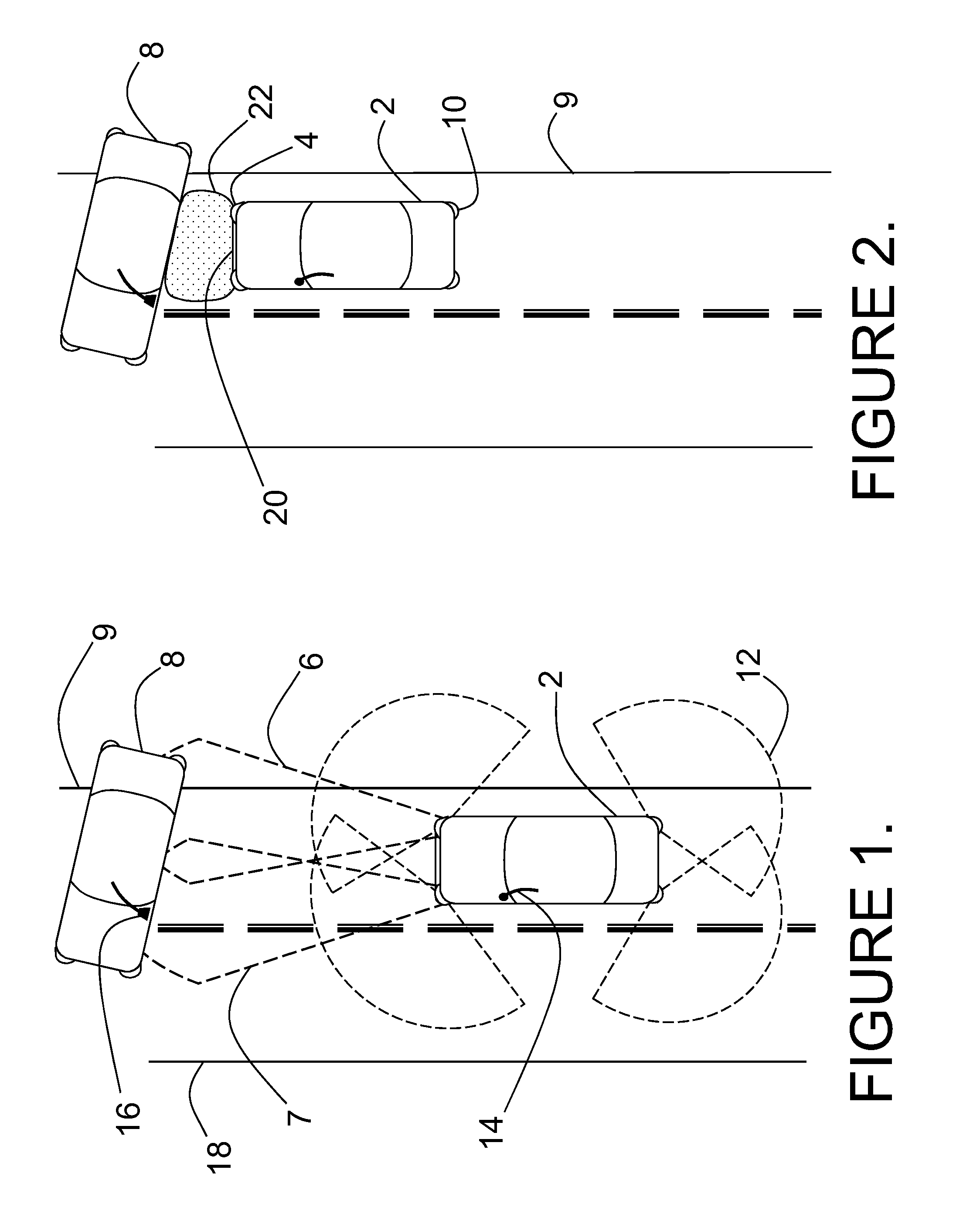
[0031]FIG. 1 depicts the impact mitigation system installed on a first vehicle 2 involved in a collision threat scenario with a second vehicle 8, which is spunout and stationary in the roadway ahead. The forward radiation pattern 6 of a long range ladar sensor embedded in a headlight assembly of first vehicle 2 is shown by dashed lines where it intersects with the driver's side of second vehicle 8, which is positioned laterally across the lane and the right edge of the roadway 9. Second vehicle 8 obstructs part of the second lane of traffic, but does not extend over the left edge of the roadway 18. A second forward radiation pattern 7 from a second long range ladar sensor embedded in a second headlight assembly is shown overlapping first radiation pattern 6. The radiation pattern 12 of a short range ladar sensor embedded in an auxiliary lamp assembly is shown projecting radially from a corner of first vehicle 2 and also at the other three corners of first vehicle 2. First vehicle 2 ...

second embodiment

[0041]FIG. 11 shows a variable ride suspension system with a coil spring 70 providing the nominal ride height for the vehicle. Coil spring 70 mounts coaxially over the outside diameter of cylinder 54 of active suspension component 61. The tire 78, rim 76, and wheel 74 are partially cut away to give a better view of the upright 68 and hub 72. Lower spring cup 75 is rigidly attached to piston 52 of active suspension component 61 and engages with the bottom end of coil spring 70. Upper spring cup 73 engages with the top of coil spring 70 and rests securely against the fender (not shown) of the vehicle indicated by dashed line 77. Fitting 62 is repositioned to be accessible through the fender of the vehicle, and umbilical 60 connects to the vehicle electrical, pneumatic, and / or hydraulic systems. FIG. 11 does not show any of the vehicle steering linkages in the interests of clarity.

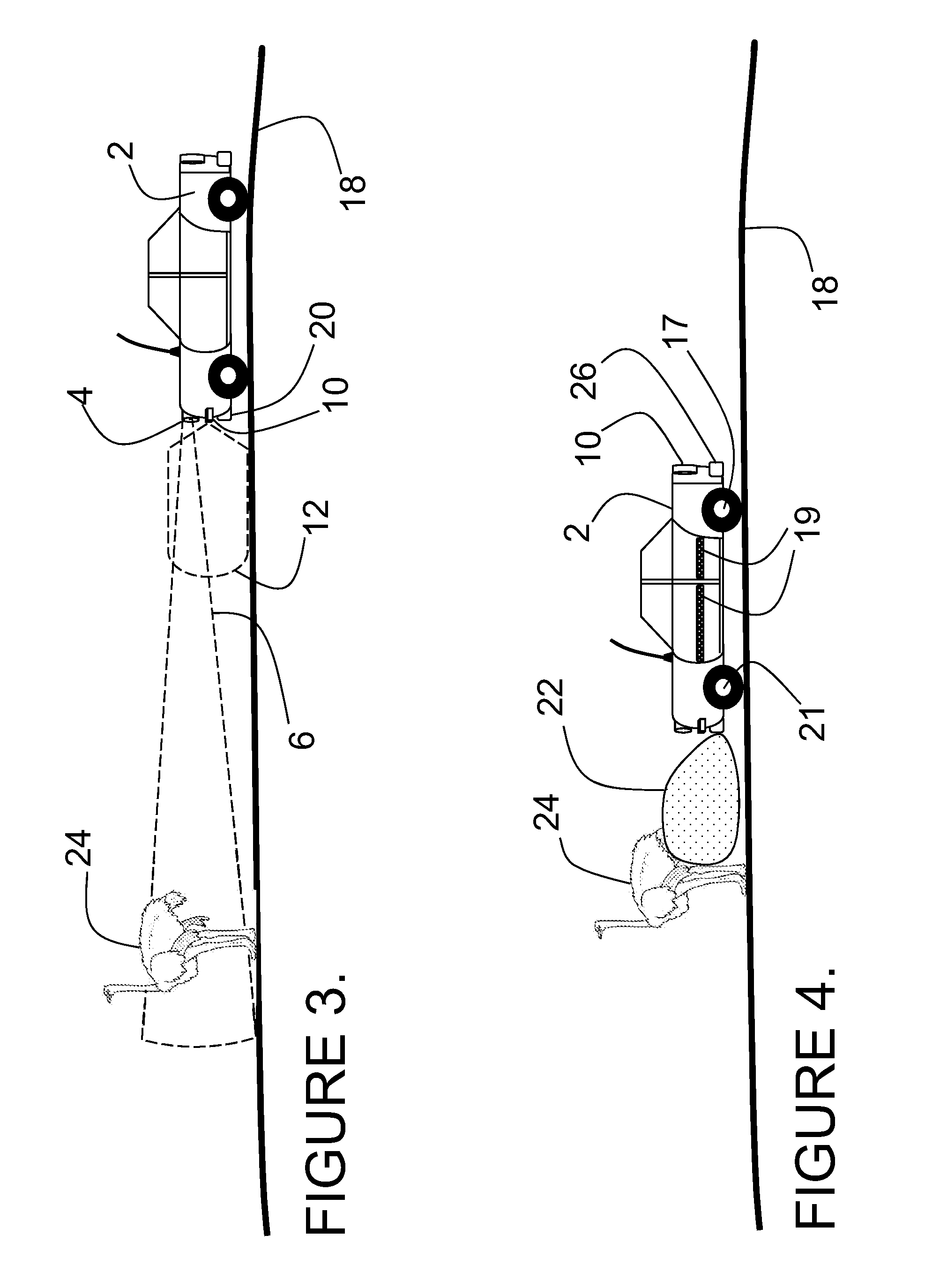
[0042]FIG. 12 shows a road hazard scenario involving first vehicle 2 and a dip 82 in the roadway 18, a pot...

third embodiment

[0043]In FIG. 13, the onboard suspension control system, knowing the depth and shape of the dip 82, and the spring rate of the coil spring or compressed air bearing the vehicle load, may simply allow the suspension to passively track through the dip 82. For some types of dips 82, and some suspension characteristics, this may be an optimum solution for the stability and control of the vehicle 2. In the case of a deep dip 82, or a soft sprung vehicle suspension, it may be necessary to actively drive the left front wheel 21 lower by using an electrical impulse into an active suspension component 61 as described in association with FIGS. 10 & 11. In an alternative embodiment, hydraulic fluid under pressure may be applied to active suspension component 61, and used to drive the left front wheel 21 lower into the dip 82. In a third embodiment, an impulse of compressed air is applied to an active suspension component 61 in order to drive the left front wheel 21 lower into the dip 82 in ord...


PUM


Abstract

A collision mitigation system is proposed which makes use of forward mounted long range ladar sensors and short range ladar sensors mounted in auxiliary lamps to identify obstacles and to predict unavoidable collisions therewith, and a duplex radio link in communication with secondary vehicles, and a number of external airbags deployable under the control of an airbag control unit, to reduce the forces of impact on the host vehicle, secondary vehicles, and bipeds and quadrupeds wandering into the roadway. A suspension modification system makes use of headlight mounted long range ladar sensors and short range ladar sensors mounted in auxiliary lamps to characterize the road surface, identify road hazards, and make adaptations to a number of active suspension components, each with the ability to absorb shock, elevate or lower the vehicle, and adjust the spring rate of the individual wheel suspensions.

Description

BACKGROUND[0001]1. Field[0002]The embodiments disclosed herein relate generally to 3-D image generation and the identification of objects, tracking of objects, road hazard avoidance, and impact mitigation. Many systems have been proposed to meet the challenge of using optical imaging and video cameras in a vehicle system to create 3-D maps of scenes and models of solid objects, and to use the 3-D database to navigate, steer, and avoid collisions with stationary or moving objects. Stereo systems, holographic capture systems, and those which acquire shape from motion, have all been proposed and in some cases demonstrated, but what is lacking is a system with the capability of rapidly capturing 3-D images of objects and roadway features in the path of a moving vehicle, or travelling on an intersecting path, and which controls and adapts the host vehicle so as to avoid collisions and road hazards, steer the best path, while at the same time mitigating the impact and damage associated wi...

Claims


Application Information

Patent Timeline
IPC IPC(8): B60G17/0195B60G17/016B60R21/013G01S17/93B60R21/01G01S7/486G01S17/04G01S17/86G01S17/89G01S17/894G01S17/931
CPCG01S17/936G08G1/166B60R1/00G01S17/023B60R21/0134G01S7/486B60R21/36G01S17/931G01S17/894B60R21/013B60G17/019B60R2021/01013G01S17/04G01S17/86G01S17/89
Inventor STETTNER, ROGERGILLILAND, PATRICKGOLDSTEIN, BARTONDUERNER, ANDREW
Owner CONTINENTAL AUTONOMOUS MOBILITY US LLC
Why Eureka
Try Eureka