High Bandwidth Multimode Optical Fiber Optimized for Multimode and Single-Mode Transmissions

a multi-mode, high-bandwidth technology, applied in the field of fiber optic transmission, can solve the problems of inability to meet the requirements of single-mode fibers, etc., to achieve the effect of simple manufacturing and low cos

Active Publication Date: 2015-07-23
DRAKA COMTEQ BV
View PDF5 Cites 12 Cited by
  • Summary
  • Abstract
  • Description
  • Claims
  • Application Information

AI Technical Summary

Benefits of technology

[0039]Thus, by minimizing the intermodal dispersion by means of a twin alpha graded-index profile, the modal bandwidth of the optical fiber at multimode wavelengths is optimized, especially for the largest numerical apertures allowed by said criterion of quality of optical communications.
[0040]In addition, the optical fiber in that alternative embodiment is simple to manufacture and costs little, since all that is needed is to adapt doping of the different fiber portions as a function of the desired refractive index profile satisfying to said criterion of quality.

Problems solved by technology

Thanks to their wider numerical aperture and core diameter, and their low modal dispersion provided by their graded-index core profile, multimode fibers can support efficiently 10 Gbps optical signals emitted by cost effective light sources based solutions (such as Vertical Cavity Surface Emitting Laser or VCSEL), whereas single-mode fibers require expensive and tolerant single-mode transceivers.
However, since the optical home network is expected to be connected to outside access networks, which mainly use single-mode technology because of longer reach requirements, the problem of interoperability with single-mode fibers needs further considerations.
In practice, multimode fibers are not designed to be interconnected with single-mode transmission systems.
These HOMs induce modal noises that degrade the quality of optical transmission.
Incoherent noise is based on the fact that, on the emitter side, the optical signal coupled into the HOMs of the fiber may suffer from modal dispersion, and so since the different modes have different propagation delay times and propagation constants, these HOMs may degrade the quality of optical transmission by overlapping delayed copies of the main optical signal on the receiver side.
Coherent noise is based on the fact that, the optical signal coupled into the HOMs of the fiber on the emitter side may generate phase mismatch with the optical signal coupled into the fundamental mode, leading to uncontrolled interferometric recombinations into the fundamental mode on the receiver side.
These interferences induce optical power fluctuation that also degrades the quality of optical transmission.
Due to the presence of these modal noises, such a standard multimode fiber is therefore not adapted to an interconnection with a single-mode optical transmission system.
However, this document does not provide any solution for minimizing modal noises caused by the HOMs of the optical fiber.
In particular, the disclosed optical fiber does not exhibit a graded-index profile (the multimode fiber portion has a step-index profile), which does not allow meeting the requirements in terms of high modal bandwidth at 850 nm.
Nor does not address the problem of reduction of modal noises at a wavelength of 1310 nm or 1550 nm.
However reducing the optical core diameter leads to degrade the quality of multimode optical transmissions.
Indeed, when a connection is carried out with a standard optical fiber (i.e. a fiber having a diameter of 50 nm or 62.5 nm), optical transmission losses are even more important where the core diameter is low, thereby significantly limiting the modal bandwidth of the optical fiber for multimode optical transmissions.
Therefore such a solution is not optimal.

Method used


Image

  • High Bandwidth Multimode Optical Fiber Optimized for Multimode and Single-Mode Transmissions
  • High Bandwidth Multimode Optical Fiber Optimized for Multimode and Single-Mode Transmissions
  • High Bandwidth Multimode Optical Fiber Optimized for Multimode and Single-Mode Transmissions

Examples


first embodiment

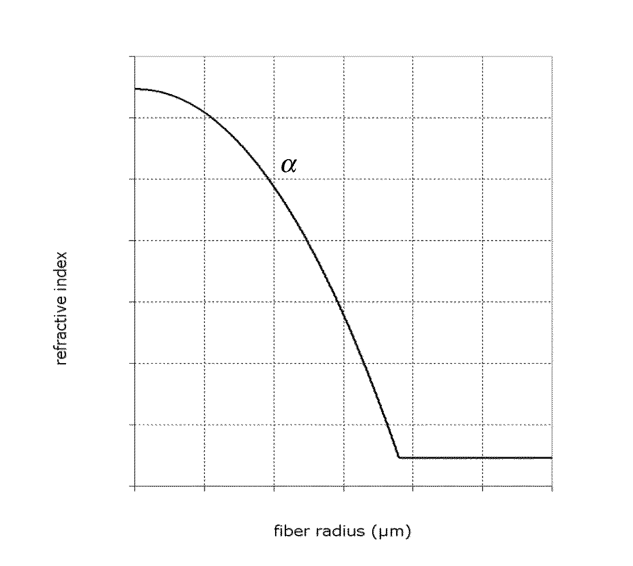
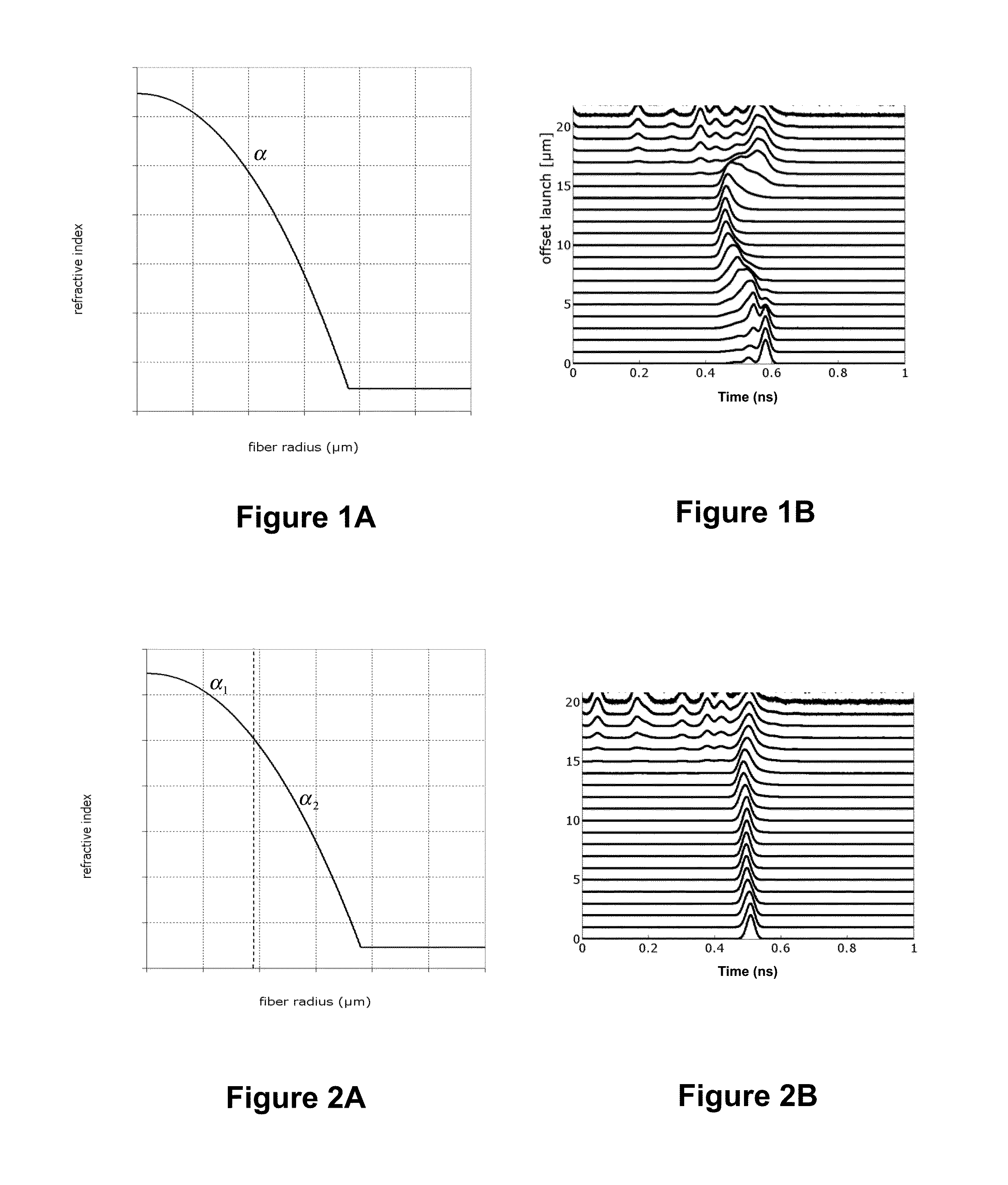
[0056]FIG. 1A depicts the refractive index profile n(r) of an optical fiber according to the invention. It describes the relationship between the refractive index value n and the distance r from the center of the optical fiber.

[0057]In that first embodiment, the optical fiber is a graded-index optical fiber having a refractive index profile n(r) defined as follow:

n(r)={n0·1-2·Δ·(ra)αr≤an0·1-2·Δr≥a(III)

where:

r is a variable representative of the radius of the optical fiber,

a is the optical core radius,

Δ is the normalized refractive index difference, with

Δ=n02-n122n02

n1 is the minimal refractive index of the optical core,

n0 is the maximal refractive index of the optical core,

α is a non-dimensional parameter that defines the index profile shape of the optical core, which is chosen between 1.9 and 2.2 so as to provide the largest bandwidth at the target operating wavelength.

[0058]The optical fiber comprises, for 0≦r≦a, an optical core implementing a single alpha graded-index profile and...

second embodiment

[0071]FIG. 2A graphically provides the refractive index profile n(r) of an optical fiber according to the invention.

[0072]In that second embodiment, the optical fiber exhibits an optical core consisted of two portions, an inner optical core and an outer optical core surrounding the inner optical core, and the refractive graded-index profile is a twin alpha graded-index profile n(r) defined by the following equation:

n(r)={n1′·1-2·Δ1·(ra)α10≤r≤rtn2′·1-2·Δ2·(ra)α2rt≤r≤an1′·1-2·Δa<rwhere:Δ1=α2Δ(rta)α2-α1α1+(α2-α1)(rta)α2Δ2=α1Δ(1-2Δ)·(α2-α1)·(rta)α2+α1n1′=n11-2Δn2′=n1·(1-2Δ)·(α1-α2)·(rta)α2-α1(1-2Δ)·((α1-α2)·(rta)α2-α1)(VI)

r is a variable representative of the radius of said optical fiber,

a is the optical core radius comprising both inner and outer optical cores,

rt is the radius of the inner optical core,

n1′ is the maximal refractive index of the inner optical core,

n2′ is the maximal refractive index of the outer optical core,

Δ1 is the normalized refractive index difference relative t...


PUM


Abstract

It is proposed an optical fiber including an optical core and an optical cladding surrounding the optical core. The optical core has a refractive graded-index profile with a minimal refractive index n1 and a maximal refractive index n0. The optical fiber has a numerical aperture NA and an optical core radius a satisfying a criterion C of quality of optical communications defined by the following equation:
C=NA−0.02×a
  • where:
  • NA=√{square root over (n02−n12)}=n0·√{square root over (2Δ)} with
Δ=n02-n122n02,
  • Δ is the normalized refractive index difference.
The minimal and maximal refractive indexes n1, n0 and the optical core radius a are chosen such that NA>0.20, a>10 μm and |C|<0.20.

Description

1. FIELD OF THE INVENTION[0001]The invention relates to fiber optic transmission, and, more specifically, to an optical fiber optimized for supporting both single-mode and multimode transmissions.2. TECHNOLOGICAL BACKGROUND[0002]An optical fiber is conventionally constituted of an optical core, which transmits an optical signal, and of an optical cladding, which confines the optical signal within the optical core. To that end the refractive index of the core, nc, is greater than the one of the cladding, ng. An optical fiber is generally characterized by a refractive index profile that associates the refractive index (n) with the radius (r) of the optical fiber: the distance r with respect to the center of the optical fiber is shown on x-axis and the difference between the refractive index at radius r and the refractive index of the optical cladding is shown on y-axis.[0003]Nowadays, two main categories of optical fibers exist: multimode fibers and single-mode fibers. In a multimode ...

Claims


Application Information

Patent Timeline
Patent Type & Authority Applications(United States)
IPC IPC(8): G02B6/028G02B6/02
CPCG02B6/02047G02B6/0281G02B6/0288G02B6/02G02B6/42
Inventor MOLIN, DENISSILLARD, PIERRESANSONETTI, PIERRE
Owner DRAKA COMTEQ BV
Why Eureka
Try Eureka