Latent fingerprint detection

a fingerprint detection and fingerprint technology, applied in the field of latent fingerprint detection, can solve the problems of difficult resolution/collection, limited fingerprint detection technology, damage to the surface, etc., and achieve the effect of reducing the duration of the activation pulse, increasing the proportion, and reducing the proportion

Inactive Publication Date: 2015-08-27
LOCKHEED MARTIN CORP
View PDF12 Cites 2 Cited by
  • Summary
  • Abstract
  • Description
  • Claims
  • Application Information

AI Technical Summary

Benefits of technology

[0011]In some variations, the trigger circuit is configured to provide an activation pulse width that causes the broad-spectrum light source to emit the desired waveband while limiting emission of wavebands which the waveband filtering device is configured to filter out.
[0026]In some variations, a step of filtering includes dissipating those portions of the broad-spectrum illumination not reflected by the first reflective optical filter. In some variations, the broad-spectrum illumination source is a flash lamp having a particular illumination time profile and the step of emitting broad-spectrum illumination includes reducing a duration of an activation pulse driving the flash lamp such that the broad-spectrum illumination emitted by the flash lamp includes an increased proportion of ultra-violet (UV) wavelengths and a reduced proportion of visible and near-infra-red wavelengths.

Problems solved by technology

Currently, fingerprint detection technologies are limited to trial-and-error techniques to locate a fingerprint-bearing surface, and yet more trial-and-error techniques to bring the fingerprint into relief against the surface to render it visible / scannable.
Latent fingerprints are very low contrast objects and therefore using only optical techniques they are difficult to resolve / collect.
Lifting latent fingerprints often requires the use of chemical techniques (i.e. processing by ninhydrin) and significant time (3+days) to lift the fingerprints, which may damage the surface and / or destroy any underlying DNA or material evidence included in the fingerprint (i.e. traces of whatever the person leaving the print may have handled previously)

Method used


Image

  • Latent fingerprint detection
  • Latent fingerprint detection
  • Latent fingerprint detection

Examples


Embodiment Construction

[0056]The following detailed description of the invention refers to the accompanying drawings. The same reference numbers in different drawings identify the same or similar elements. Also, the following detailed description does not limit the techniques, devices, and solutions described herein. Instead, the scope of the techniques, devices, and solutions described herein is defined by the appended claims and equivalents thereof.

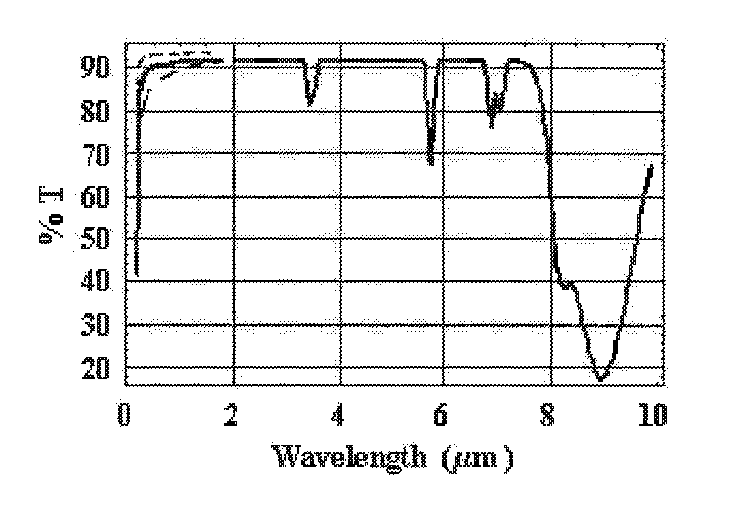
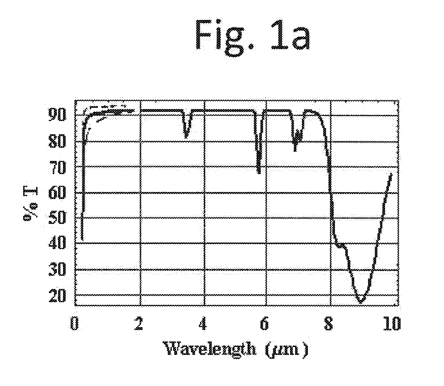
[0057]For fingerprint oils / waxes, there are specific electro-optical radiation domains where absorption of the fingerprint oils / waxes significantly exceeds the absorption of a background material. The image contrast of latent fingerprints is directly linked, but not limited, to their absorption (scattering, for example, may also contribute to contrast). An absorption significantly exceeding the absorption of a background material means a level of difference in the absorption that allows for a contrast level sufficient to permit imaging / detection of the finger...


PUM

PropertyMeasurementUnit
wavelengthsaaaaaaaaaa
light wavelengthsaaaaaaaaaa

Abstract

Systems, devices, and methods for detecting a contaminant on a substrate are discussed herein. Variations of such systems, devices, and methods may include one or more illumination sources that emit illumination at one or more desired wavelength ranges to illuminate one or more areas on the substrate; where the desired wavelength range is one that is absorbed by the contaminant while causing the substrate to fluoresce. Such fluorescence may be detected with a visible-spectrum detector, which will also detect the contaminant as a darker contrast area against the fluorescence. In some variations, an illumination source includes a broad-spectrum light source and a waveband filtering device that filters all but the desired illumination waveband out of the broad-spectrum light generated by the broad-spectrum light source.

Description

PRIORITY[0001]The present Application claims benefit of priority to U.S. provisional application 61 / 573,077, filed Aug. 26, 2011; 61 / 530,306, filed Sep. 1, 2011; 61 / 538,020, filed Sep. 22, 2011; 61 / 602,950, filed Feb. 24, 2012; 61 / 602,956, filed Feb. 24, 2012; 61 / 606,886, filed Mar. 5, 2012; and 61 / 606,898, filed Mar. 5, 2012, the entire contents of all of which are hereby incorporated by reference.TECHNICAL BACKGROUND[0002]Currently, fingerprint detection technologies are limited to trial-and-error techniques to locate a fingerprint-bearing surface, and yet more trial-and-error techniques to bring the fingerprint into relief against the surface to render it visible / scannable.[0003]Optical detection of latent fingerprints is critically dependent on image contrast. Latent fingerprints are very low contrast objects and therefore using only optical techniques they are difficult to resolve / collect. Lifting latent fingerprints often requires the use of chemical techniques (i.e. processin...

Claims


Application Information

Patent Timeline
Patent Type & Authority Applications(United States)
IPC IPC(8): G01N21/64G01N21/31G06V10/143G06V40/13
CPCG01N21/31G01N21/6447A61B5/0071A61B5/1172G06V40/13G06V40/155G06V10/143H04N23/50H04N23/56H04N5/33
Inventor MIESAK, EDWARD J.
Owner LOCKHEED MARTIN CORP
Why Eureka
Try Eureka