Proximity effect correction in a charged particle lithography system

a lithography system and proximity effect technology, applied in the field of proximity effect correction, can solve the problems of numerical instability of conventional methods for numerically approximating a corrected layout pattern, inability to determine the correct layout pattern analytically from the exposed pattern and the base proximity effect function, and inability to accurately calculate high frequency components

Active Publication Date: 2015-08-27
ASML NETHERLANDS BV
View PDF5 Cites 1 Cited by
  • Summary
  • Abstract
  • Description
  • Claims
  • Application Information

AI Technical Summary

Benefits of technology

[0010]According to the method of the present invention the corrected layout pattern is calculated based on deconvolution of the digital layout pattern with the modified proximity effect function instead of with the base proximity effect function, so that negative influences of high frequency components in the digital layout pattern on the numerical stability during calculation of said deconvolution are substantially reduced. As a result, a more constant and accurate corrected layout pattern may be obtained.
[0054]In an embodiment a radius in which the dose of the background dose map varies is proportional to a radius of influence the beta proximity function, said radius preferably substantially corresponding to β. Thus the value of the magnitude of the radius in which the background dose map varies is closer to the magnitude of the radius of influence of the beta proximity function than to the magnitude of the radius of influence of the alpha proximity effect function, e.g. closer to β than toα. This allows the background dose map to be represented using relative large polygons (for example rectangles on a regular grid) of the background with sizes of the same order as said radius. The dimensions of the individual features are typically much smaller than said radius. Because the background dose map can thus be represented using relatively large and few polygons the data volume of the data structure can remain relative small. The magnitude of the radius in which the background dose map varies may be equal to or substantially equal to β.

Problems solved by technology

In general, a corrected layout pattern cannot be determined analytically from the exposed pattern and the base proximity effect function because the exposed pattern which is formed on the target is a somewhat blurred version of the digital layout pattern and lacks information on high frequency components that may have been present in the digit layout.
Conventional techniques for numerically approximating a corrected layout pattern suffer from numerical instability when high frequency components, e.g. densely spaced features such as lines or contacts, are present in the digital layout pattern.
When these conventional techniques are used, the high frequency components may be calculated incorrectly or omitted from the corrected layout pattern altogether, as a result of which the high frequency components of the digital layout pattern may not be transferred correctly onto the target.

Method used


Image

  • Proximity effect correction in a charged particle lithography system
  • Proximity effect correction in a charged particle lithography system
  • Proximity effect correction in a charged particle lithography system

Examples


Embodiment Construction

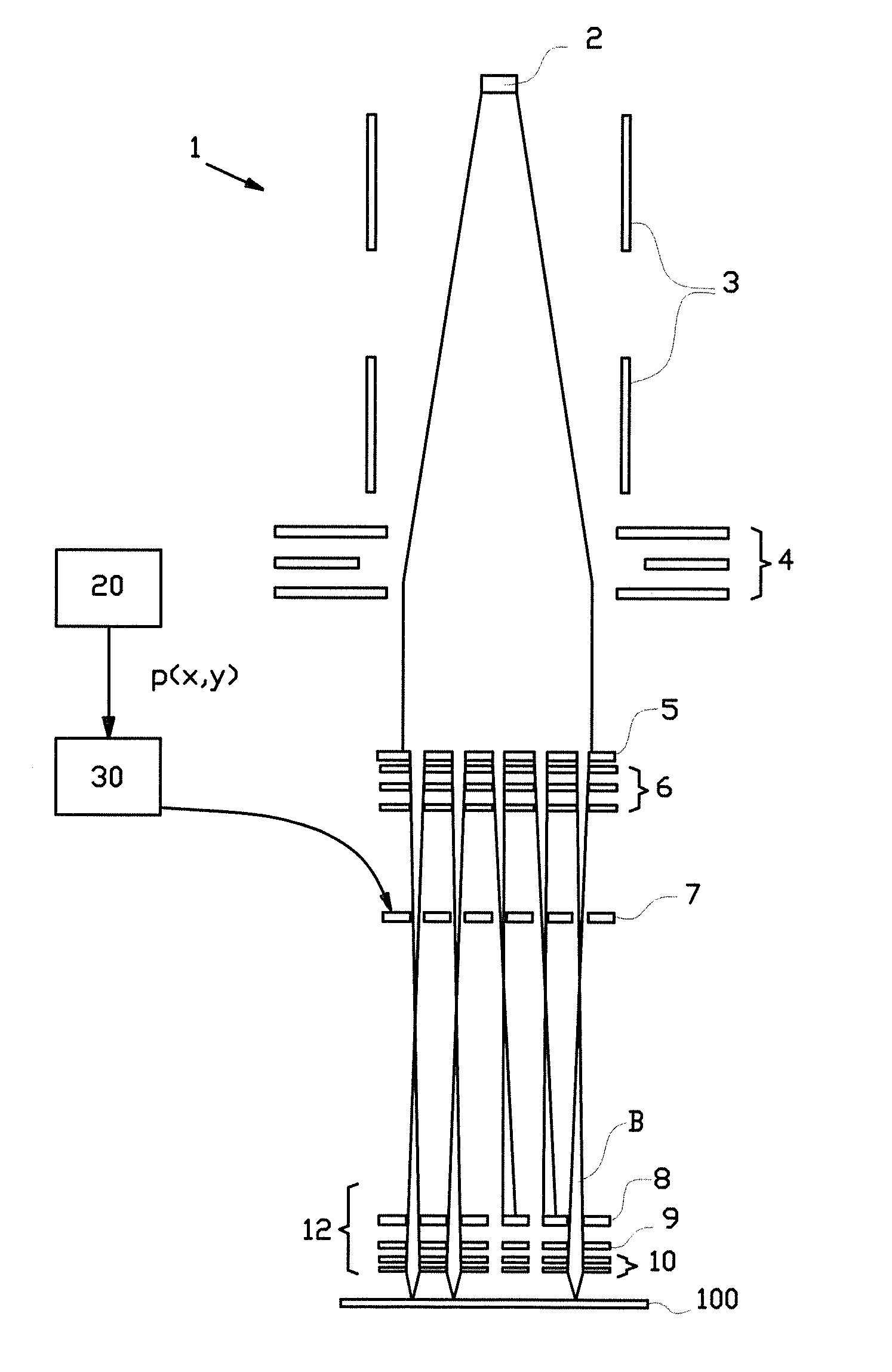
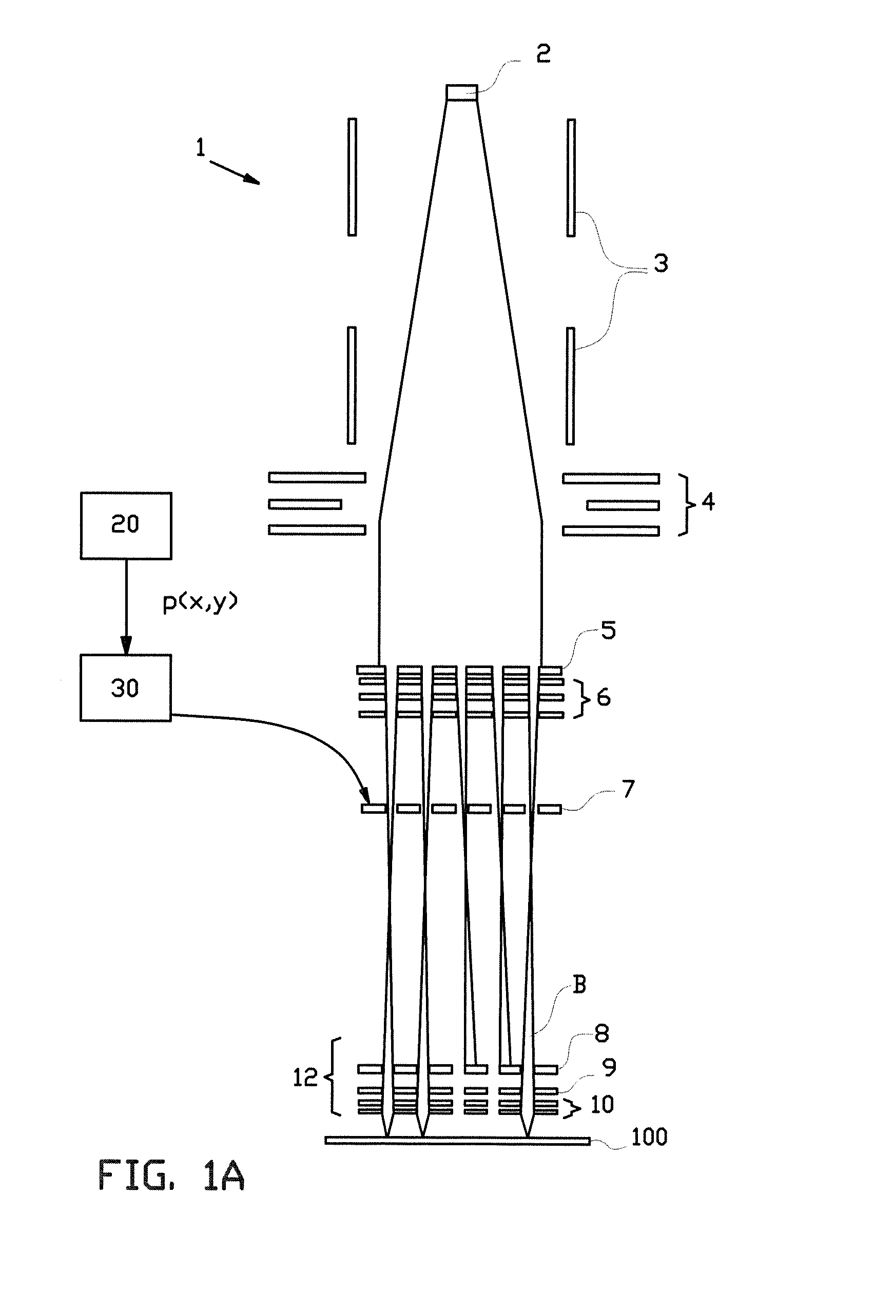
[0074]FIG. 1A schematically shows a multi-beamlet charged particle lithography system 1 according to the present invention. The system comprises a charged particle beam source 2 which emits a charged particle beam which traverses a double octopole 3 and collimator lens 4 before impinging on an aperture array 5. The aperture array then splits the beam into a multitude of charged particle beams which are condensed by condenser array 6. At beam blanker array 7 individual beams may be blanked, i.e. may be deflected such that they encounter beam stop array 8 later on in their trajectories instead of passing through apertures in beam stop array 8. An electronic processor 30 is arranged for receiving, from a digital storage 20, a digital layout p(x,y) of a pattern to be transferred to the target, and for calculating a corrected layout pattern which compensates at least partially for the proximity effect as described in more detail below. The electronic processor comprises a controller whic...


PUM


Abstract

The invention relates to a method for performing charged particle beam proximity effect correction, comprising the steps of: receiving a digital layout pattern to be patterned onto a target using one or more charged particle beams; selecting a base proximity function comprising a sum of an alpha and a beta proximity function, wherein said alpha proximity function models a short range proximity effect and said beta proximity function models a long range proximity effect, wherein a constant η is defined as a ratio between the beta proximity function and the alpha proximity function in said sum, with 0<η<1;determining a modified proximity function which corresponds to said base proximity effect function wherein the alpha proximity function has been replaced by a Dirac delta function, andusing an electronic processor, performing a deconvolution of the digital layout pattern with the modified proximity function to produce a corrected layout pattern.

Description

BACKGROUND[0001]The invention relates to a method for proximity effect correction, e.g. as may be performed in a charged particle lithography system. Typically, in a charged particle beam lithography system at least one beam of charged particles is directed onto a resist-layer of a wafer to form a desired pattern in the resist. The achievable pattern resolution within the resist depends on how well the spatial charged particle energy deposition can be controlled within the resist. When a charged particle beam is directed onto a position on a substrate which is coated with resist, some of the incident charged particles are scattered on their trajectories through the resist.[0002]In forward scattering, a charged particle of the beam of charged particles may collide with an electron of the substrate or the resist. This causes the charged particle to be deflected from its trajectory and to deposit part of its energy in the substrate or resist.[0003]The charged particles may also collide...

Claims


Application Information

Patent Timeline
Patent Type & Authority Applications(United States)
IPC IPC(8): H01J37/317H01J37/04H01J37/30
CPCH01J37/3174H01J37/3007H01J2237/043H01J2237/31715H01J37/045H01J37/3177H01J2237/31769H01J37/3026H01J2237/0435H01J2237/3175
Inventor WIELAND, MARCO JAN-JACO
Owner ASML NETHERLANDS BV
Why Eureka
Try Eureka