
Negative ion-based neutral beam injector

a neutron-based, neutral beam technology, applied in the direction of accelerators, masers, laser details, etc., can solve the problems of difficult to produce negative hydrogen ions than their positive counterparts, difficult for newly born negative ions, and significantly less beam current achieved so far , to achieve the effect of facilitating beam homogeneity

Active Publication Date: 2015-08-27
TAE TECH INC
View PDF1 Cites 24 Cited by
  • Summary
  • Abstract
  • Description
  • Claims
  • Application Information

AI Technical Summary

Benefits of technology

The invention is a new design for a high voltage accelerator that is used in ion sources. The accelerator is separated from the ion source by a transition zone, which removes most of the unwanted particles from the beam. This prevents damage to the accelerator and ensures the beam is focused properly. The design also reduces the amount of gas and particles that can affect the accelerator, resulting in a more stable and efficient beam.

Problems solved by technology

However, beam currents achieved so far are significantly less than that produced quite routinely by positive ion sources.
Therefore, it is much more difficult to produce negative hydrogen ions than their positive counterparts.
It is also quite difficult for newly born negative ions to reach an extraction region without collisions with energetic electrons which, with very high probability, will cause the loss of the extra loosely bound electron.
Extracting H− ions from plasma to form a beam is likewise more complicated than with H+ ions, since the negative ions will be accompanied by a much larger current of electrons unless suppression measures are employed.
The main issues for the LHD ion sources is a blocking of cesium, which is seeded to the arc chamber, by the tungsten sputtered from filaments and the decrease of high voltage holding capacity when operated in the high-power long pulse regime.
At present, high energy neutral beam injectors, which are under development for next phase fusion devices, such as, e.g., the ITER tokomak, have not demonstrated stable operation at a desired 1 MeV energy and steady state or continuous wave (CW) operation with high enough current.

Method used


Image

  • Negative ion-based neutral beam injector
  • Negative ion-based neutral beam injector
  • Negative ion-based neutral beam injector

Examples


Embodiment Construction

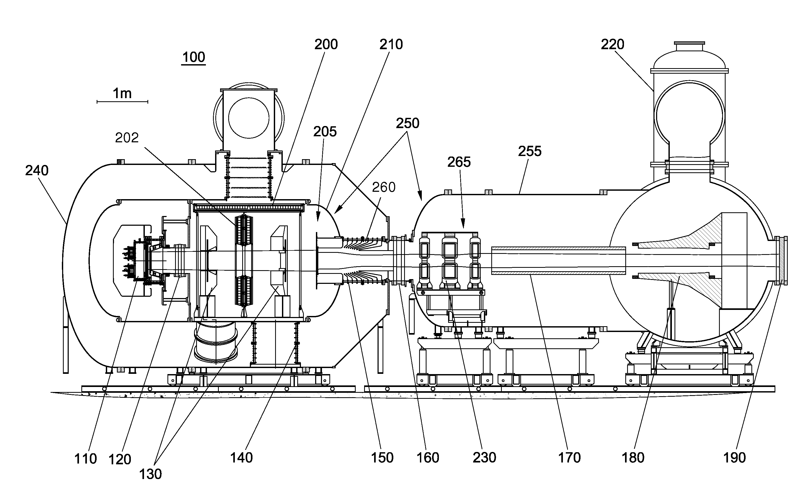
[0058]Each of the additional features and teachings disclosed below can be utilized separately or in conjunction with other features and teachings to provide a new negative ion-based neutral beam injector. Representative examples of the embodiments described herein, which examples utilize many of these additional features and teachings both separately and in combination, will now be described in further detail with reference to the attached drawings. This detailed description is merely intended to teach a person of skill in the art further details for practicing preferred aspects of the present teachings and is not intended to limit the scope of the invention. Therefore, combinations of features and steps disclosed in the following detail description may not be necessary to practice the invention in the broadest sense, and are instead taught merely to particularly describe representative examples of the present teachings.

[0059]Moreover, the various features of the representative exa...


PUM


Abstract

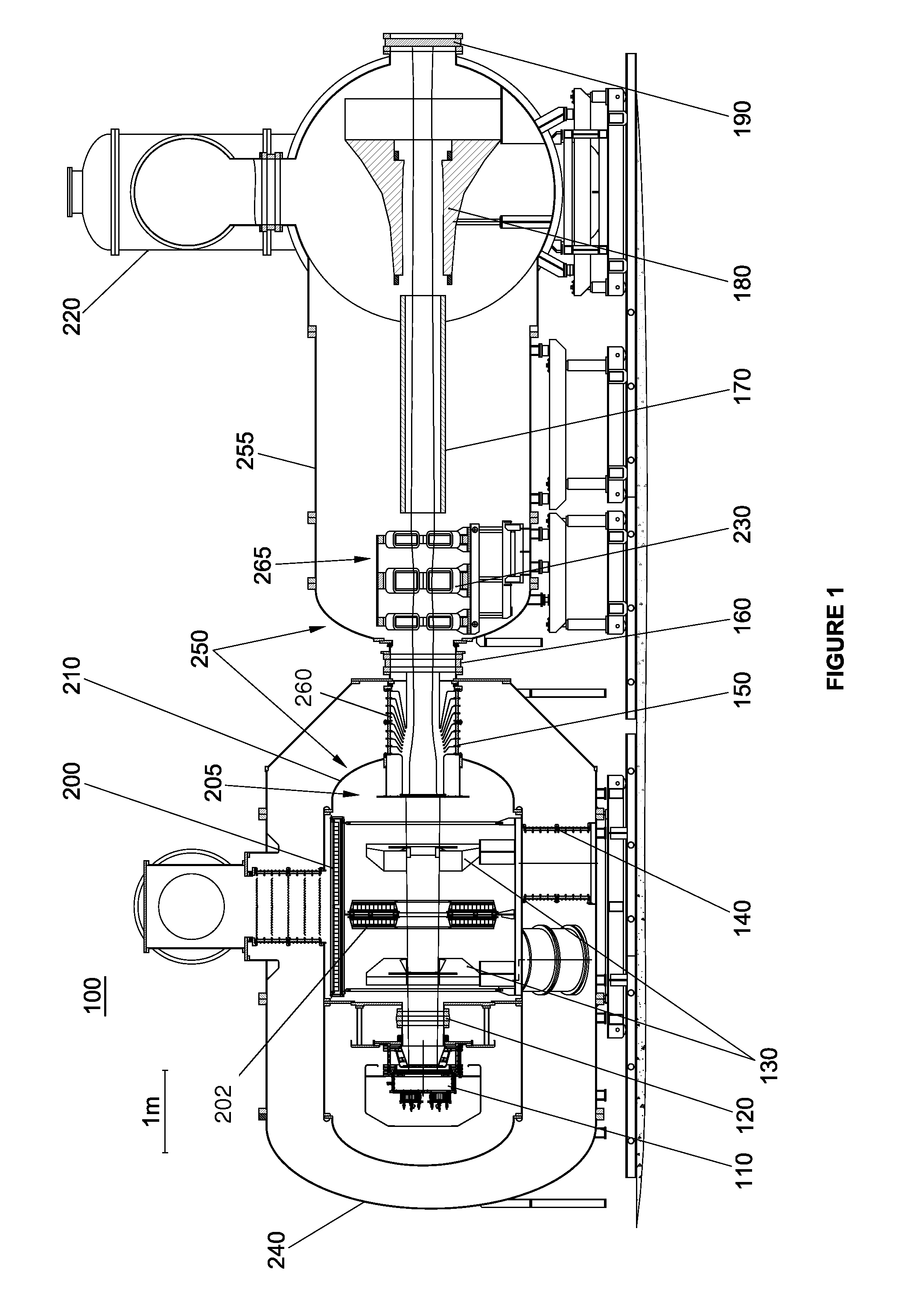
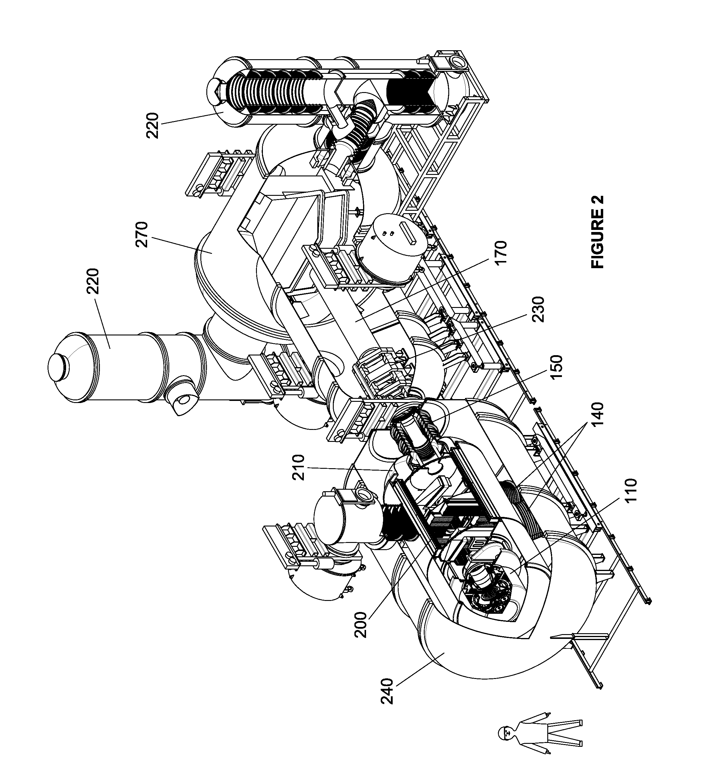
A negative ion-based neutral beam injector comprising a negative ion source, accelerator and neutralizer to produce about a 5 MW neutral beam with energy of about 0.50 to 1.0 MeV. The ions produced by the ion source are pre-accelerated before injection into a high energy accelerator by an electrostatic multi-aperture grid pre-accelerator, which is used to extract ion beams from the plasma and accelerate to some fraction of the required beam energy. The beam from the ion source passes through a pair of deflecting magnets, which enable the beam to shift off axis before entering the high energy accelerator. After acceleration to full energy, the beam enters the neutralizer where it is partially converted into a neutral beam. The remaining ion species are separated by a magnet and directed into electrostatic energy converters. The neutral beam passes through a gate valve and enters a plasma chamber.

Description

CROSS-REFERENCE TO RELATED APPLICATIONS[0001]The subject application is a continuation of International Application No. PCT / US2013 / 058093, filed on Sep. 4, 2013, which claims priority to U.S. Provisional Patent Application Ser. No. 61 / 775,444, filed on Mar. 8, 2013, both of which are incorporated by reference herein in their entirety for all purposes.FIELD[0002]The subject matter described herein relates generally to neutral beam injectors and, more particularly, to a neutral beam injector based on negative ions.BACKGROUND[0003]Until quite recently, the neutral beams used in magnetic fusion research, material processing, etching, sterilization and other applications were all formed from positive ions. Positive hydrogen isotope ions were extracted and accelerated from gas discharge plasma by electrostatic fields. Immediately after the ground plane of the accelerator, they entered a gas cell, where they underwent both charge exchange reactions to acquire an electron and impact ionizat...

Claims


Application Information

Patent Timeline
Patent Type & Authority Applications(United States)
IPC IPC(8): H05H3/02
CPCH05H3/02G21K1/00
Inventor BELCHENKO, YURI I.BURDAKOV, ALEXANDER V.DAVYDENKO, VLADIMIR I.DIMOV, GENNADY I.IVANOV, ALEXANDER A.KOBETS, VALEERY V.SMIRNOV, ARTEM N.BINDERBAUER, MICHL W.SEVIER, DONALD L.RICHARDSON, TERRENCE E.
Owner TAE TECH INC
Learn More