Manufacturing method for rare-earth magnet

a rare earth magnet and manufacturing method technology, applied in the direction of magnetic materials, magnetic bodies, transportation and packaging, etc., can solve the problems of excessive swelling at the central part at the side, insufficient deformation energy directed to the crystalline orientation, and cracks at the side faces of plastic deformed compacts, etc., to achieve excellent magnetic characteristics and high degree of orientation

Active Publication Date: 2015-10-01
TOYOTA JIDOSHA KK
View PDF0 Cites 11 Cited by
  • Summary
  • Abstract
  • Description
  • Claims
  • Application Information

AI Technical Summary

Benefits of technology

[0041]As can be understood from the above descriptions, according to the method for manufacturing a rare-earth magnet of the present invention, when a compact is placed in a plastic processing mold for hot deformation processing, a part of the compact only is firstly allowed to come into contact with a side face of a cavity of the plastic processing mold to receive pressure therefrom, and at this time another part of the com

Problems solved by technology

Meanwhile, as the amount of heat generated at a motor increases because of the trend to more compact motors and higher current density, rare-earth magnets included in the motors also are required to have improved heat resistance, and one of important research challenges in the relating technical field is how to keep magnetic characteristics of a magnet at high temperatures.
Such hot deformation processing can give magnetic anisotropy to the compact, but has a problem that, during the course of the compact being crushed while being plastic-deformed by the pressure from the upper and lower punches in the hot deformation processing, the plastic deformed compact tends to generate cracks (including micro-cracks) at the side faces.
This results from excessive deformation of a part of the compact that comes into contact with the upper and lower punches, and accordingly excessive swelling occurs at the central part at the side faces, i.e., the deformation shaped like a barrel as one reason.
Such cracks cause the processing deformation that is formed to improve the degree of orientation to be open at the positions of the cracks, thus failing to direct the deformation energy to the crystalline orientation sufficiently.
As a result, an orientational magnet obtained cannot have high degree of orientation (such high degree of orientation m

Method used


Image

  • Manufacturing method for rare-earth magnet
  • Manufacturing method for rare-earth magnet
  • Manufacturing method for rare-earth magnet

Examples


embodiment 1

of Manufacturing Method of a Rare-Earth Magnet and Such a Rare-Earth Magnet

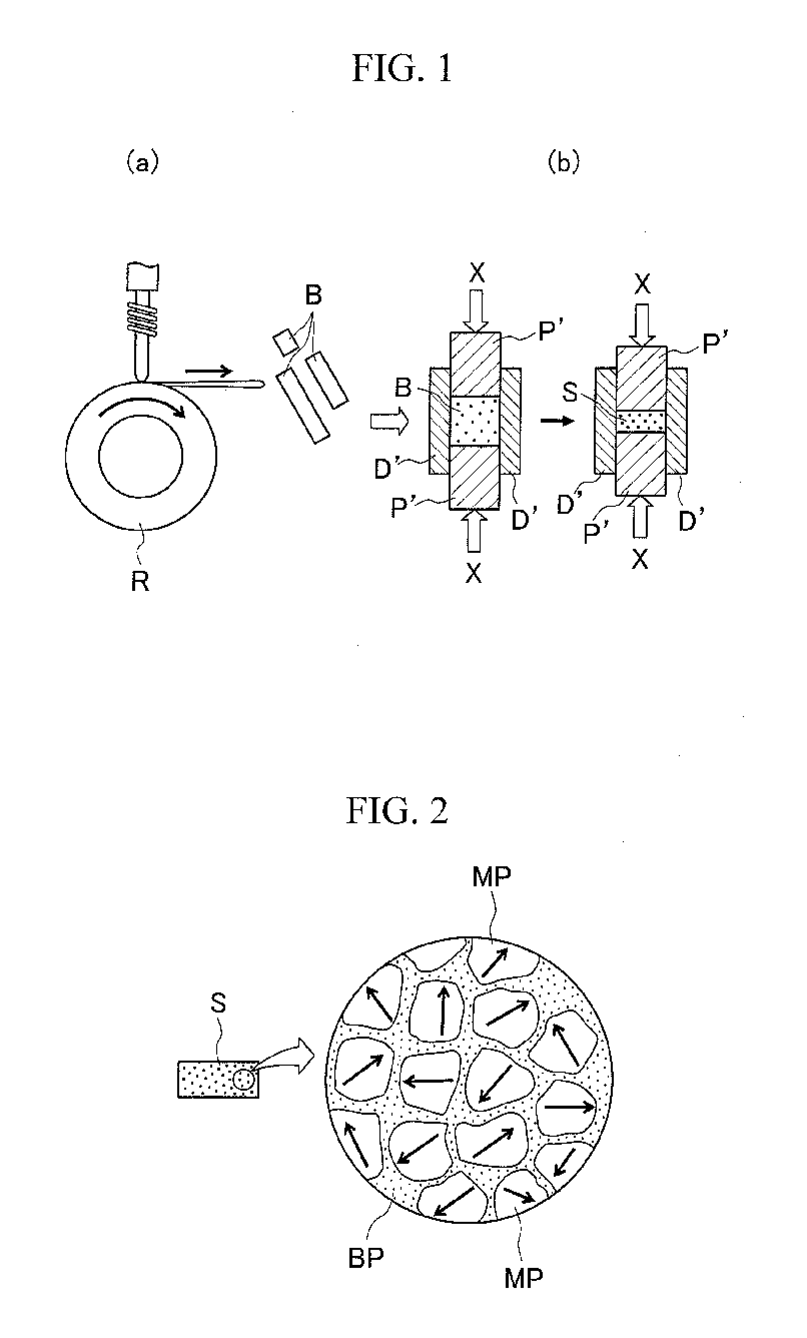
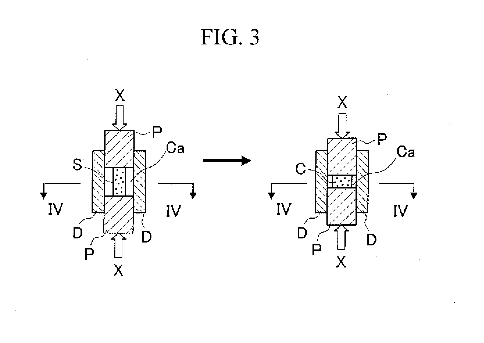
[0056]FIGS. 1a, b schematically illustrate a first step of a method for manufacturing a rare-earth magnet of the present invention in this order, and FIG. 2 illustrates the micro-structure of a compact that is manufactured by the first step. FIG. 3 schematically illustrates a second step of Embodiment 1 of the manufacturing method of the present invention.

[0057]As illustrated in FIG. 1a, alloy ingot is molten at a high frequency, and a molten composition giving a rare-earth magnet is injected to a copper roll R to manufacture a melt-spun ribbon B (rapidly quenched ribbon) by a melt-spun method using a single roll in an oven (not illustrated) under an Ar gas atmosphere at reduced pressure of 50 kPa or lower, for example. The melt-spun ribbon obtained is then coarse-ground.

[0058]Among the melt-spun ribbons that are coarse-ground, a melt-spun ribbon B having a maximum grain size of about 200 nm or less is select...

embodiment 2

of Manufacturing Method of a Rare-Earth Magnet and Such a Rare-Earth Magnet

[0075]FIG. 7 schematically illustrates a manufacturing method of a rare-earth magnet that is Embodiment 2, where FIG. 7a illustrates from the state where a compact is placed in a cavity of a first plastic processing mold to the state of an intermediary body of the orientational magnet as well as the cavity after hot deformation processing, and FIG. 7b illustrates the state where the intermediary body is placed in a cavity of a second plastic processing mold to the state of the orientational magnet as well as the cavity after hot deformation processing. For easy understanding, FIGS. 7a and b illustrate cross sections of cavities Ca1 and Ca2 of dies D1 and D2 making up the two plastic processing molds and the compact S, the intermediary body C′ of the orientational magnet and the orientational magnet C only.

[0076]The illustrated manufacturing method that is Embodiment 2 is to perform hot deformation processing ...


PUM

PropertyMeasurementUnit
Percent by massaaaaaaaaaa
Nanoscale particle sizeaaaaaaaaaa
Dimensionaaaaaaaaaa

Abstract

Provided is a method for manufacturing a rare-earth magnet capable of manufacturing a rare-earth magnet with high degree of orientation by sufficient plastic deformation while suppressing cracks at the side faces of a compact that is plastic-deformed during the hot deformation processing. The method includes a step of preparing a compact S, preparing a plastic processing mold including a die D in which a cavity Ca is provided, and punches P that are slidable in the cavity Ca, the cavity Ca having a cross section that is larger in cross-sectional dimensions than a cross section of the compact S that is orthogonal to a pressing direction by the punches P; and a step of placing the compact S in the cavity Ca and performing hot deformation processing, thus manufacturing an orientational magnet C. Let that W1 denotes a length of a short side of the cross section of the cavity Ca and t1 denotes a length of a side of the cross section of the compact S that is placed in the cavity Ca, the side corresponding to the short side of the cavity Ca, t1/W1 is within a range of 0.55 to 0.85, and from some stage during the hot deformation processing, a part of the compact S is constrained at a side face of the cavity Ca so that deformation of the compact is suppressed, but another part of the compact is in a non-constraint state.

Description

TECHNICAL FIELD[0001]The present invention relates to a method for manufacturing a rare-earth magnet in the form of an orientational magnet formed by hot deformation processing.BACKGROUND ART[0002]Rare-earth magnets containing rare-earth elements such as lanthanoide are called permanent magnets as well, and are used for motors making up a hard disk and a MRI as well as for driving motors for hybrid vehicles, electric vehicles and the like.[0003]Indexes for magnet performance of such rare-earth magnets include remanence (residual flux density) and a coercive force. Meanwhile, as the amount of heat generated at a motor increases because of the trend to more compact motors and higher current density, rare-earth magnets included in the motors also are required to have improved heat resistance, and one of important research challenges in the relating technical field is how to keep magnetic characteristics of a magnet at high temperatures.[0004]The following briefly describes one example ...

Claims


Application Information

Patent Timeline
IPC IPC(8): H01F41/02B22F3/02H01F1/08C22C33/02B22F3/17H01F1/057B22F3/14C22C38/00
CPCH01F41/0266B22F3/14B22F3/02C22C38/005H01F1/08C22C33/02B22F3/17H01F1/0576C22C38/002C22C38/00C22C2202/02H01F41/0273B22F2998/10B22F2999/00B22F1/07B22F2009/048B22F2202/05
Inventor MIYAMOTO, NORITAKAICHIGOZAKI, DAISUKESHOJI, TETSUYAHOSHINA, EISUKEKANO, AKIRAYAMASHITA, OSAMU
Owner TOYOTA JIDOSHA KK
Why Eureka
Try Eureka