Metal Powder Processing Equipment

a technology of metal powder and processing equipment, which is applied in the direction of metal-working machine components, manufacturing tools, additive manufacturing, etc., can solve the problems of damage to the cutting tool, reduced processing efficiency, and reduced cutting efficiency, so as to prolong the life of the cutting tool and improve the quality of the cutting surface. , the effect of reducing the processing tim

Active Publication Date: 2015-10-08
MATSUURA MACHINERY
View PDF6 Cites 5 Cited by
  • Summary
  • Abstract
  • Description
  • Claims
  • Application Information

AI Technical Summary

Benefits of technology

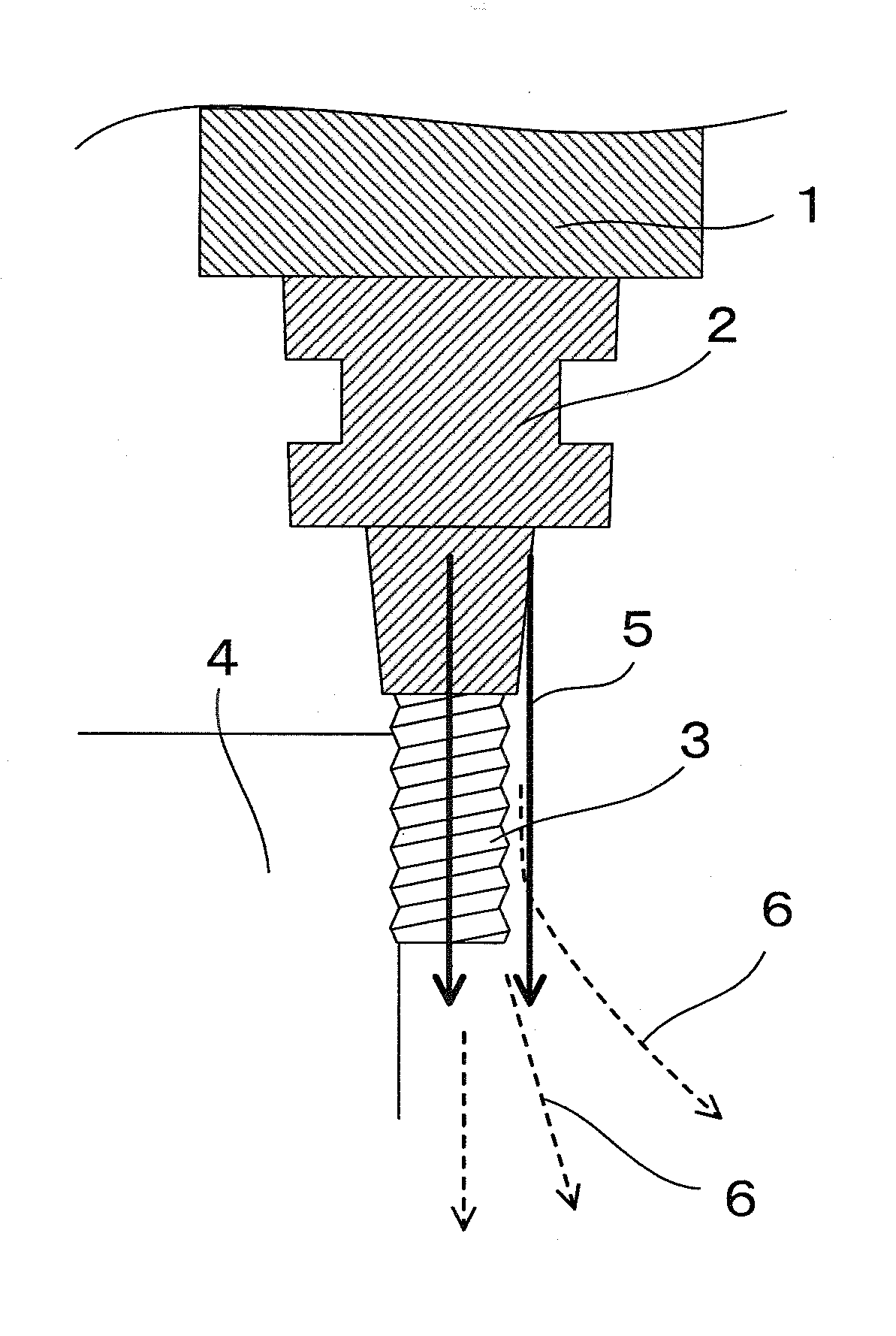
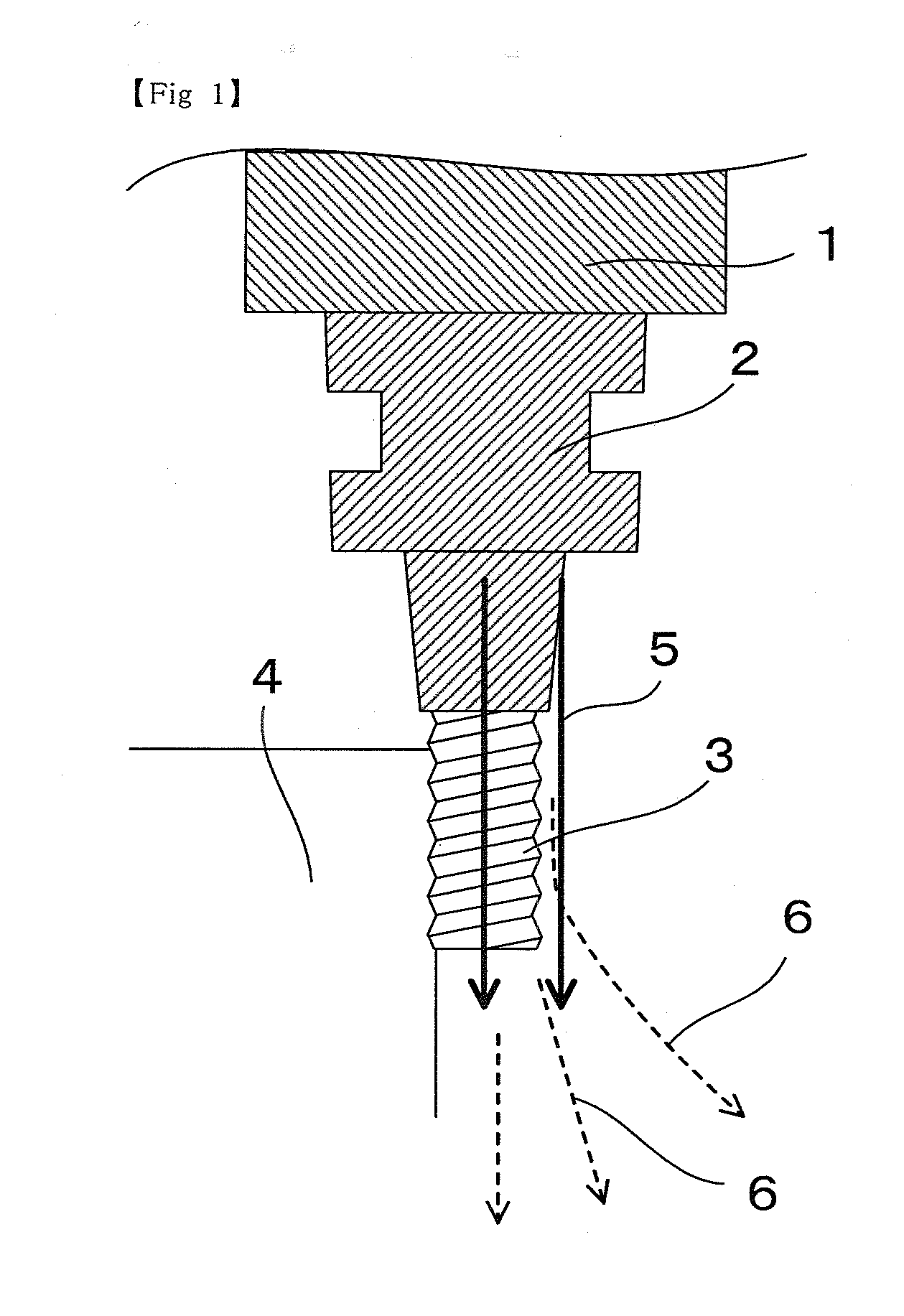
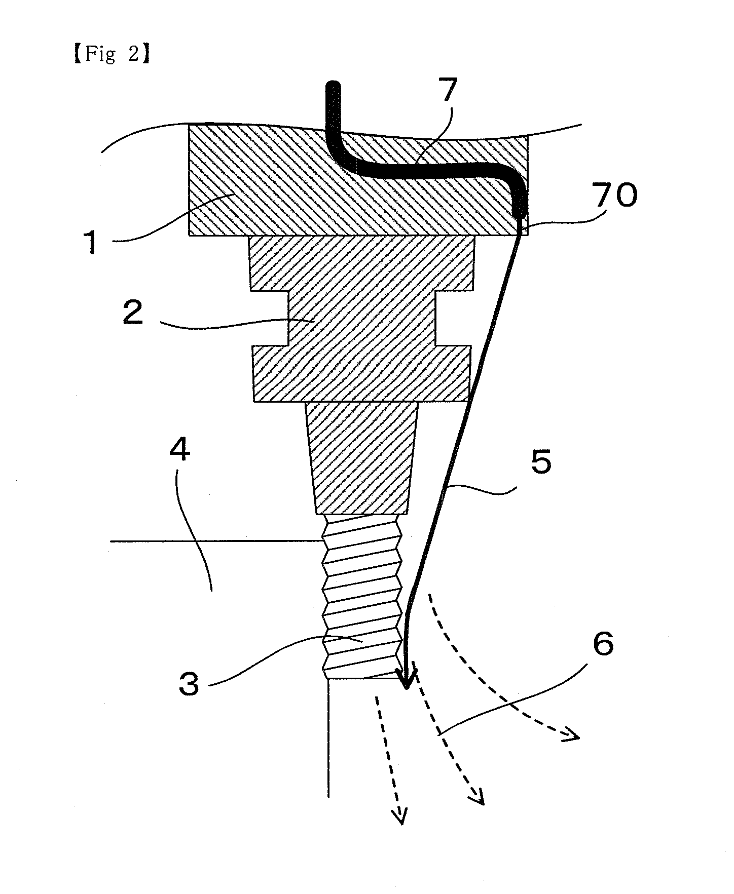
[0015]According to the present invention based on the above-mentioned basic configuration, the unmolded powder and cut powder are scattered from a cutting edge of the cutting tool or the vicinity thereof by the air flow generated by the metal powder processing equipment itself, and further, the life of the cutting tool is prolonged and quality of the cut surface is improved while processing time can be also shortened by securing smooth rotation of the cutting tool.

Problems solved by technology

In the case of continuing the cutting process in a state in which the unmolded powder and cut powder remain, not only the life of the cutting tool is extremely shortened but also damage occurs on the cutting tool because of the unmolded powder and cut powder remaining at a cutting edge of the cutting tool.
Additionally, in the case where cutting process is executed being tangled with the unmolded powder and cut powder, a cut surface may be affected and a smooth surface may not be obtained.
As a result, even quality of the processed surface is deteriorated.
However, according to this method, the extra tool for removing the unmolded powder and cut powder is required to be installed, and it is unavoidable to cause not only complication of an equipment structure and driving control but also complication of the processing step.

Method used


Image

  • Metal Powder Processing Equipment
  • Metal Powder Processing Equipment
  • Metal Powder Processing Equipment

Examples


embodiment

[0036]According to another embodiment, one or a plurality of rotor blades 21 that blows air flow 5 to a cutting tool 3 side is arranged to a peripheral wall of a side surface of a tool holder 2 for generating air flow 5 at vicinity of the said surface of the cutting tool 3 in a longitudinal direction as illustrated in FIG. 5.

[0037]In the case of such an embodiment, unmolded powder and cut powder 6 likely to adhere to the cutting tool 3 can be scattered by an extremely simple configuration of attaching the rotor blades (fins) 21 to the peripheral wall of the side surface of the tool holder 2.

[0038]As illustrated in FIG. 5, the rotor blades (fins) 21 generally adopts a configuration in which an inclination angle is sequentially increased in the rotational direction as is the case with a propeller, and preferably a plurality of rotor blades is provided along the peripheral wall of the tool holder 2. Further, in the case where a plane angle of the rotor blades (fins) 21 is about 45 degr...


PUM

PropertyMeasurementUnit
plane angleaaaaaaaaaa
areaaaaaaaaaaa
Air pressureaaaaaaaaaa

Abstract

In metal powder processing equipment where metal powder is sequentially laminated on a table inside a chamber and laser beam melting or electron beam melting, and shaping by a cutting tool subsequent to the melting are performed, unmolded powder remaining at the time of the melting and cut powder generated by the cutting can be scattered by generating air flow with respect to the cutting tool from either side of a main shaft or a tool holder. As a result, life of the cutting tool is prolonged and quality of a cut surface can be improved.

Description

TECHNICAL FIELD[0001]The present invention relates to metal powder processing equipment in which metal powder is sequentially laminated on a table inside a chamber, and laser beam melting or electron beam melting, and shaping by a cutting tool subsequent to the melting are performed.BACKGROUND ART[0002]In the above-mentioned melting step, unmolded powder remains near a molded object, and powdery cut chips generated by the cutting remain near a molded object in the above-mentioned cutting process step.[0003]In the case of continuing the cutting process in a state in which the unmolded powder and cut powder remain, not only the life of the cutting tool is extremely shortened but also damage occurs on the cutting tool because of the unmolded powder and cut powder remaining at a cutting edge of the cutting tool.[0004]Additionally, in the case where cutting process is executed being tangled with the unmolded powder and cut powder, a cut surface may be affected and a smooth surface may no...

Claims


Application Information

Patent Timeline
Patent Type & Authority Applications(United States)
IPC IPC(8): B23K26/14B23K15/00B23K26/34
CPCB23K26/1405B23K26/345B33Y40/00B33Y30/00B23K15/0086B23Q11/005B22F3/24B22F2003/247Y02P10/25B22F10/28B22F10/68B22F10/66
Inventor AMAYA, KOICHIKATO, TOSHIHIKOMATSUBARA, HIDETOYOSHIDA, MITSUYOSHI
Owner MATSUURA MACHINERY
Why Eureka
Try Eureka