Integrated medical imaging system

Inactive Publication Date: 2015-10-29
CALCULA TECH
View PDF20 Cites 11 Cited by
  • Summary
  • Abstract
  • Description
  • Claims
  • Application Information

AI Technical Summary

Benefits of technology

[0024]In various embodiments, processing the image data may involve gamma correcting the image data, denoising the image data, filtering the image data, depixelizating the image data, white balancing the image data, and/or formatting the image data for display to a display device. Optionally, the method may further involve, before advancing the elongate sheath into the human or animal subject, inserting the sheath into a lumen of a medical device, where the sheath is advanced into the subject by advancing the medical device into the subject. In some embodiments, the medical device is configured for use in a ureter of the human or animal subject, and the advancing step involves advancing the medical with the inserted sheath into the ureter. In some embodiments, the medical device comprises a camera system. In some embodiments, inserting the sheath comprises mating a mating feature on the camera body with a corresponding mating feature on a proximal end of the medic

Problems solved by technology

Many medical procedures and tools that may benefit from direct visualization are incompatible with the use of any currently available endoscope.
Difficult uretheral catheterizations, for example, may benefit from direct visualization, but Fole

Method used


Image

  • Integrated medical imaging system
  • Integrated medical imaging system
  • Integrated medical imaging system

Examples


Embodiment Construction

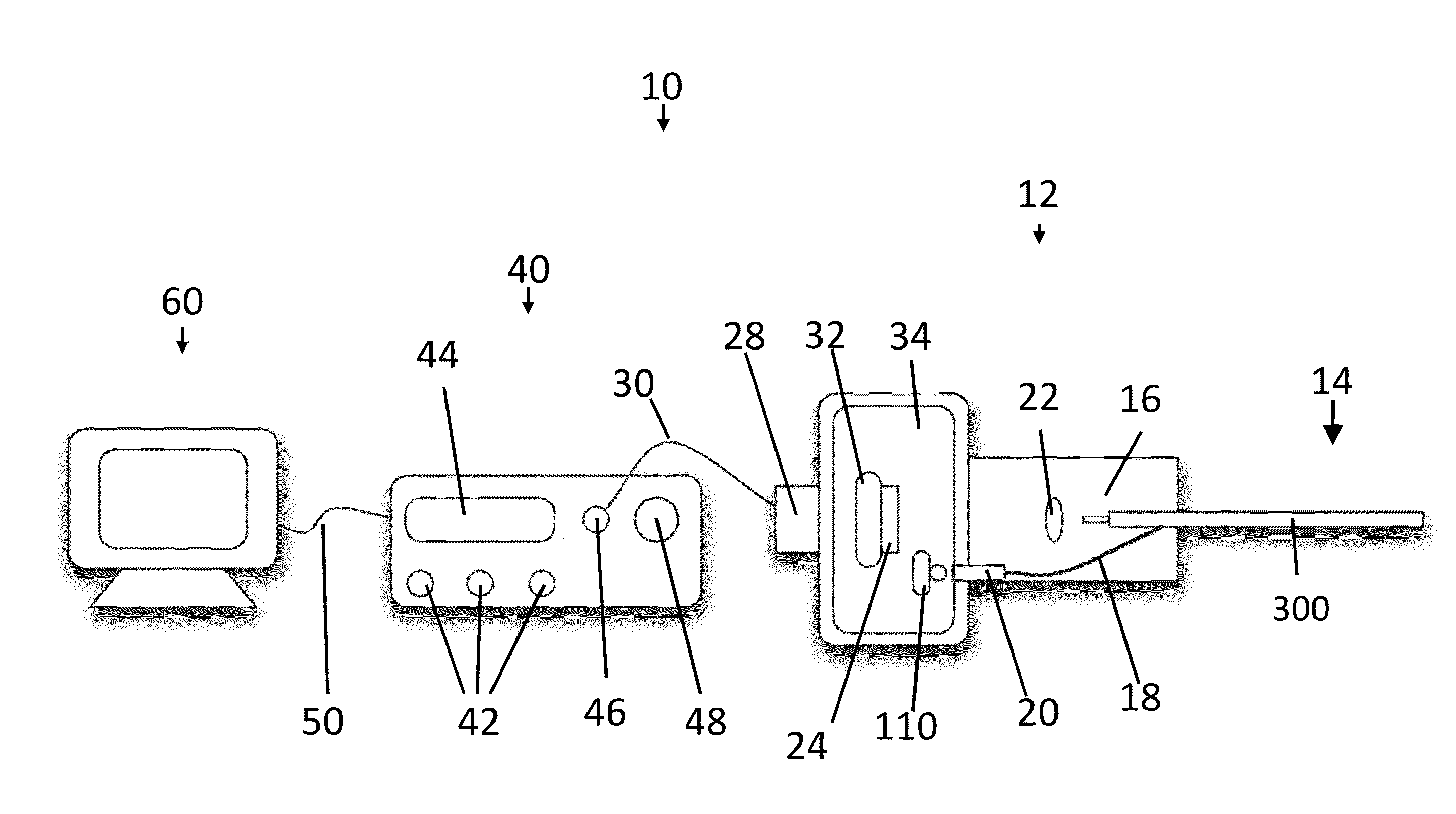
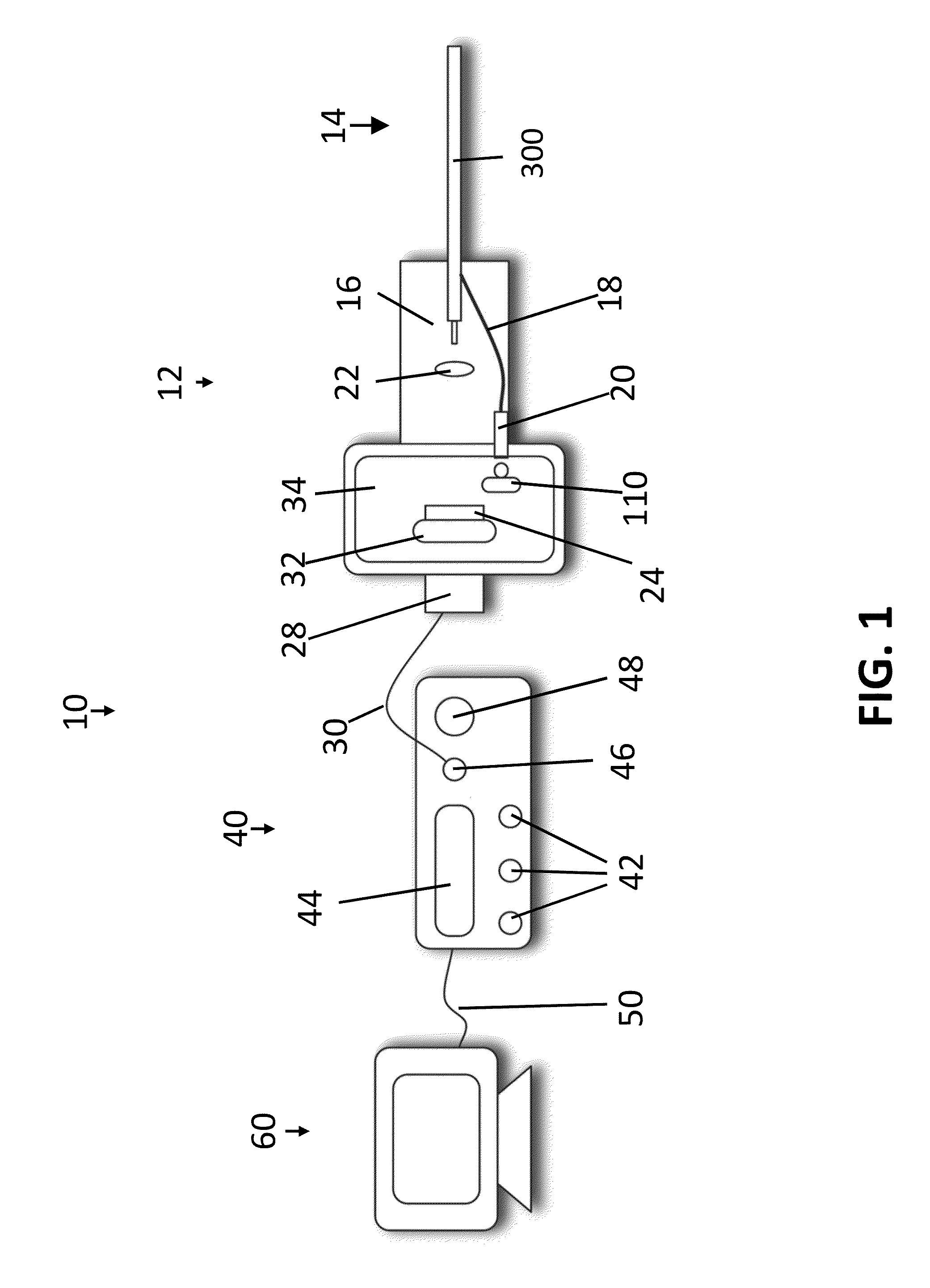
[0038]Referring to FIG. 1, in one embodiment, a medical imaging system 10 may include a fiber optic camera 12, a video processing console 40 and a display monitor 60. In alternative embodiments, system 10 may include only camera 12 and video processing console 40 or only camera 12. However, for ease of description, monitor 60 and video processing console 40 are described as part of system 10 in this embodiment. (Neither FIG. 1 nor any subsequent figures are drawn to scale. Various devices and parts of devices in various figures may be magnified, relative to other devices and parts, to enhance clarity of the figures.)

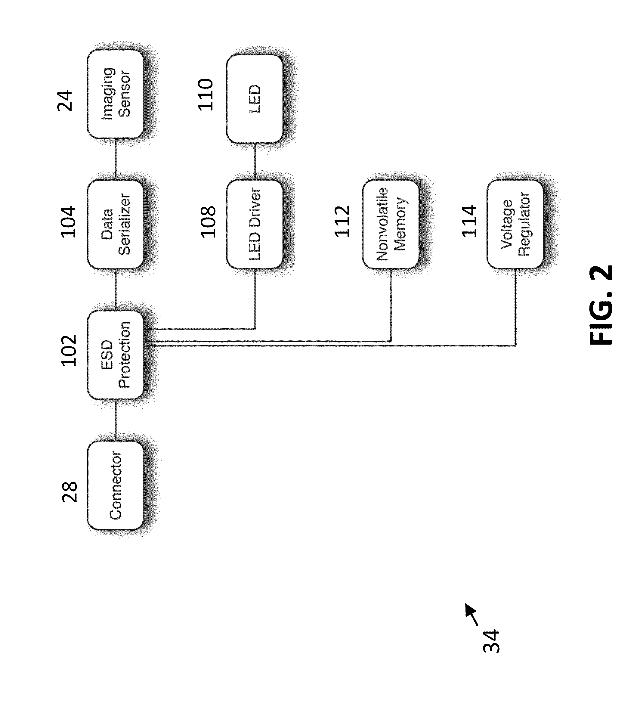
[0039]Fiber optic camera 12 may include a fiber bundle 14, which includes an outer sheath 300 (or “bundle sheath”) that houses a fiber optic imaging bundle 16 and multiple fiber optic illumination fibers 18. Sheath 300 also typically houses a lens at or near its distal end (not visible in FIG. 1). Fiber bundle 14 is fixedly attached to a camera body 36 (or “mechanical ho...


PUM


Abstract

A fiber optic camera system may include a fiber optic camera and a video processing console. The camera may include an elongate sheath having a proximal end and a distal end, and the sheath may contain one or more illumination optical fibers and an imaging bundle having at least one fiber optic clad and multiple fiber optic cores. The camera may further include a camera body fixedly attached to the proximal end of the elongate sheath, and the camera body may contain an imaging sensor optically coupled to a proximal end of the imaging bundle and configured to generate image data and an illumination source optically coupled to proximal ends of the illumination fibers. In some embodiments, the camera body has no connection member for connecting a secondary illumination source to the camera.

Description

CROSS-REFERENCE TO RELATED APPLICATIONS[0001]This application claims priority to U.S. Provisional Patent Application No. 61 / 983,419, filed on Apr. 23, 2014, the disclosure of which is hereby fully incorporated by reference.FIELD OF THE DISCLOSURE[0002]The present disclosure is related to visualization devices for medical and / or surgical procedures. More specifically, the disclosure is related to flexible, elongate cameras for visualizing within a human or animal body.BACKGROUND[0003]Visualization of tissues, structures and tools in medical practice is often critical to a successful clinical outcome. During traditional open surgeries and procedures, this was relatively trivial—the practitioner simply looked into the body. With the advent of minimally invasive and endoscopic procedures, however, advances in visualization have become necessary to properly view the surgical field. To that end, advances in visualization technology have paralleled the miniaturization of surgical tools and...

Claims


Application Information

Patent Timeline
IPC IPC(8): A61B1/04A61B1/307A61B1/00A61B1/07
CPCA61B1/042A61B1/00121A61B1/307A61B1/07A61B1/00167A61B1/0669A61B1/00009A61B1/00062
Inventor GAL, DAVIDBONNEAU, RAYMOND ARTHUR
Owner CALCULA TECH
Why Eureka
Try Eureka