Absorbant and reflecting biocompatible dyes for highly accurate medical implants

a biocompatible dye and high-accuracy technology, applied in the direction of impression caps, instruments, prostheses, etc., can solve the problems of not preventing tissue regeneration or remodeling, affecting the quality of medical implants, so as to increase the strength of 3d printed tissue and increase the strength of manufactured parts.

Active Publication Date: 2015-11-05
RICE UNIV
View PDF5 Cites 10 Cited by
  • Summary
  • Abstract
  • Description
  • Claims
  • Application Information

AI Technical Summary

Benefits of technology

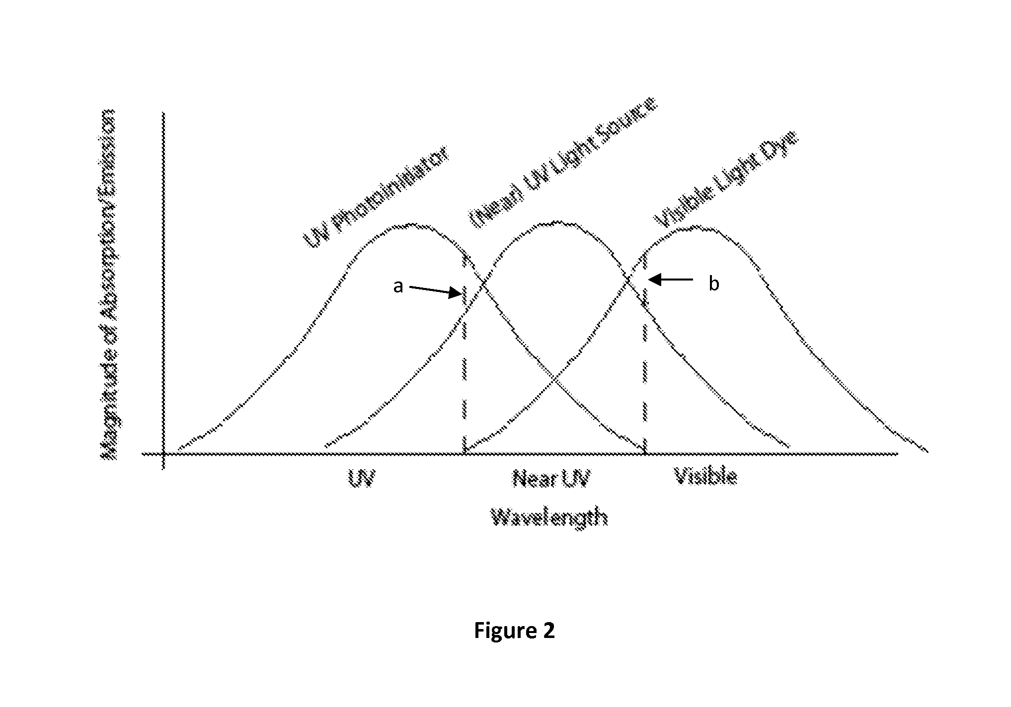
[0020]A photo-initiator package for a liquid light polymerizable composition for use in tissue engineering applications comprises a first photo-initiator and a second photo-initiator wherein the first photo-initiator cures the composition when exposed to a first light source in an additive manufacturing device and the second photo-initiator limits the transmission of light that activates the first photo-initiator in the additive manufacturing device, and wherein the second photo-initiator is activated when exposed to a second light source used to post-cure the composition. In one embodiment, one or both of the first and second photo-initiators are an acylphosphine oxide. According to yet another embodiment, the first photo-initiator is BAPO and the second photo-initiator is Bis(.eta.5-2,4-cylcopentadien-1-yl)-bis(2,6-difluoro-3-(1H-pyrrol-1-yl)-phenyl) titanium. Also contemplated herein is a method of increasing the strength of a 3D printed tissue engineering part comprises mixing a light-polymerizable polymer with a first photo-initiator and a second photo-initiator, wherein the second photo-initiator limits the transmission of light that activates the first photo-initiator, exposing the mixture to localized light to cure the polymer, and post-curing the product in a light bath, wherein the light in the light bath activates the second photo-initiator to increase the strength of the manufactured part.

Problems solved by technology

If the walls between porous spaces of the implant or scaffold are too thick they may not resorb, and thereby become a barrier to remodeling.
If the materials degrade, their byproducts need to be non-toxic and easily metabolized so that they do not prevent tissue regeneration or remodeling.
However, concerns may arise as to the resorbability of the crystals in the host's body.
For example, accurate rendering makes it more likely that complex internal pore structures such as those described above and other can be created.
However, post-curing handling of low molecular weight scaffolds or implants could be problematic and thus the ideal rendering method would minimize any post-curing handling necessary.
While stereolithographic rendering of implants and scaffolds has been demonstrated, limitations in the commercially available devices has thus far resulted in relatively low accuracy levels.
For example, accuracy and resolution of conventional stereolithographic rendering devices may not allow the devices to produce scaffold or implant surface features such as pores and pore openings at the low end of the optimum geometry scale.
While conventional stereolithographic rendering devices may be able to produce orthogonally oriented pore structures in implants and scaffolds, they may not be able to provide sufficient resolution to produce obliquely oriented pores.
Moreover, stereolithographic rendering may also have various other limitations in the context of manufacturing of implants or scaffolds.
The drawing speed is typically not fast enough to simultaneously draw all pixels in the layer, which may make it difficult to control pixel to pixel crosslinking within the layer and / or over-curing or stitching between layers as the implant or scaffold is rendered.
Also, conventional stereolithography devices may not provide a way to modulate the amount of energy at one spot versus another within a layer to, for example, control the depth of polymerization and level or strength of over-curing.
Furthermore, dyes that are effective against ultraviolet transmission and USP grade are even harder to come by.
However, in its effectiveness, there is an inevitable downside, while titanium dioxide is a strong ultraviolet absorber, it also has strong scattering properties, which leads to inadvertent curing, thereby decreasing resolution in the xy-plane and potentially z-plane as well.

Method used


Image

  • Absorbant and reflecting biocompatible dyes for highly accurate medical implants
  • Absorbant and reflecting biocompatible dyes for highly accurate medical implants
  • Absorbant and reflecting biocompatible dyes for highly accurate medical implants

Examples


example 1

[0100]A first embodiment focused on the calibration of the cDLP additive manufacturing system to accurately render scaffolds with predictable properties of resorption, cell attachment and proliferation, host incorporation, and tissue regeneration.

[0101]FIG. 8 illustrates isometric, front, and top views, respectively, of an exemplary scaffold 500. The goal of the calibration study was to calibrate the cDLP system for the additive manufacturing of scaffolds with the “plate and post” geometry of scaffold 500. In the embodiment, the cylindrical test scaffold was 6.0 millimeters in diameter and 12.4 millimeters in length. The diameter of the vertical channels 510 was 800 micrometers. The plates 520 were 400 micrometers thick and 800 micrometers apart from each other. The posts 530 between the plates, were 600 micrometers in diameter. The calibration of the cDLP process consisted of at least six steps.

[0102]The first step in the calibration procedure was to polymerize single layers of the...

example 2

[0116]This embodiment was implemented on the Perfactory® UV device having a 60 millimeter lens. A relatively small amount of dye was necessary (for example, 0.01 to 0.2 wt %) of overall resin mass. The dye used in this study was at a greater concentration than is typically used in industrial applications, up to 0.5% of overall polymer mass. It is important that the dye be biocompatible. In this study, a yellow chromium azo dye was used. The amount of initiator used in this study was 2% of Irgacure® 819 (BASF (Ciba), Florham Park, N.J.). The substance used in this study to reduce the viscosity of the resin was diethyl fumarate (DEF), the monomer precursor of PPF.

[0117]The designed (i.e., in CAD software) plate thickness and post diameter were 0.4 millimeters and 0.6 millimeters, respectively. The ten-plate scaffolds generated had an average plate thickness of 0.43±0.02 millimeters, and average post thickness of 0.63±0.01 millimeters. The precision of the features (i.e., low standard ...

example 3

[0118]For this embodiment, the Perfactory device used had a 60 millimeter lens providing an in-plane native resolution of 71 micrometers and 35.5 micrometers utilizing pixel-shifting. The resorptive polymer, polypropylene fumarate) (PPF), was used. A yellow chromium azo dye was added. The initiator used in this embodiment was Irgacure® 819 (BASF (Ciba), Florham Park, N.J.). The substance used to reduce the viscosity of the PPF was diethyl fumarate, the monomer precursor of PPF. The between plane energy settings were calibrated to achieve a voxel height of 120 micrometers when using a 200 mW / dm2 irradiance, and an exposure time of 120-240 s. The scaffold shape was composed in a Computer Aided Design (CAD) program and 6 scaffolds were rendered using a 120 s exposure. 2 scaffolds were later rendered using a 240 s exposure. 10 measurements of the overall diameter of each scaffold were collected using calipers. The intended scaffold diameter was 6 mm.

[0119]The scaffolds (n=6) rendered us...


PUM

PropertyMeasurementUnit
sizesaaaaaaaaaa
molecular weightaaaaaaaaaa

Abstract

A light-polymerizable composition for additive manufacturing of resorbable scaffolds and implants comprising a biocompatible resin. The biocompatible resin includes a combination of photo-initiators or a dye-initiator package tailored to manufacture implants with the desired physical and chemical properties. A dye or other constituent controls between layer (z) resolution of the manufactured part built in an additive manufacturing device. A light absorber or other constituent controls within layer (x-y) resolution of the manufactured part.

Description

CROSS REFERENCE TO RELATED APPLICATIONS[0001]This application is a continuation-in-part of International Patent Application PCT / US2011 / 048620 filed on Aug. 22, 2011 which claims the benefit of U.S. Provisional Patent Application Nos. 61 / 373,353 filed on Aug. 20, 2010 and 61 / 491,194 filed on May 29, 2011, which are incorporated herein by reference. This application also claims priority to U.S. Provisional Patent Application No. 61 / 731,843 filed on Nov. 30, 2012.FEDERAL FUNDING NOTICE[0002]The inventions were made with government support under grant Nos. R01-DE013740 and R01-AR061460 awarded by the National Institutes of Health (NIH). The Government has certain rights in the inventions.BACKGROUND[0003]Tissue engineering is an attempt to regenerate a defect in tissue that is larger than the unaided body can regenerate on its own. In most cases tissue engineering requires technology for the creation of three components: implants (often referred to as scaffolds), cells and growth factors...

Claims


Application Information

Patent Timeline
Patent Type & Authority Applications(United States)
IPC IPC(8): A61L27/18
CPCA61L27/18A61L27/50A61L27/56G02B26/0833B33Y30/00B33Y80/00B33Y50/00B29C64/129A61L27/14G02B26/00A61L27/40B29C64/135A61L27/60
Inventor DEAN, H. DAVIDSIBLANI, ALMOTT, ERIC J.FISHER, JOHN P.WANG, MARTHA O.MIKOS, ANTONIOS G.
Owner RICE UNIV
Why Eureka
Try Eureka