Iron-based powder for powder metallurgy

Active Publication Date: 2015-11-05
JFE STEEL CORP
View PDF7 Cites 10 Cited by
  • Summary
  • Abstract
  • Description
  • Claims
  • Application Information

AI Technical Summary

Benefits of technology

[0042]The present invention provides an iron-based powder for powder metallurgy that evenly fills thin-walled cavities and keeps the ejection force aft

Problems solved by technology

The iron-based powder, additive powder, and lubricant, however, have different characteristics (shape, particle size, and the like), and thus flowability of the mixed powder is not uniform.
(a) The iron-based powder, additive powder, and lubricant unevenly distribute locally due to the influence of vibration or dropping during transport of the mixed powder to a storage hopper.
Therefore, the apparent density of the mixed powder is not uniform across the upper and lower portions of the hopper.
In other words, with conventional techniques, it is extremely dif

Method used


Image

  • Iron-based powder for powder metallurgy
  • Iron-based powder for powder metallurgy

Examples


Example

[0086]As a comparative example, the same combination as for Inventive Example 2 in Table 1 was heated and mixed under the same conditions as for Inventive Example 1 and then cooled to 80° C. and charged into a nauta mixer. At this time, dust was collected at the discharge port of the high-speed mixer, and carbon black was added and mixed. Next, under the same conditions as the above Inventive Examples, the filling performance of the iron-based powder and the tensile strength and impact value of the sintered body were evaluated. The evaluation results for Comparative Example 1 are shown in Table 2.

[0087]Furthermore, the same combination as for Inventive Example 2 in Table 1 was heated and mixed under the same conditions as for Inventive Example 1 and then cooled to 100° C. and charged into a nauta mixer. At this time, dust was collected at the discharge port of the high-speed mixer, and carbon black was added and mixed. Next, under the same conditions as Comparative Example 1, the fi...

Example

[0089]As shown in Table 2, Comparative Example 1 had a poor appearance. Comparative Example 2 had a large filling variation and a poor appearance. Comparative Example 3 had a small filling variation yet a poor appearance. Furthermore, the sintered body strength was lower than for Comparative Example 1.

REFERENCE SIGNS LIST

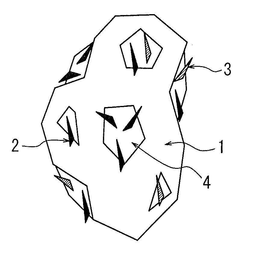
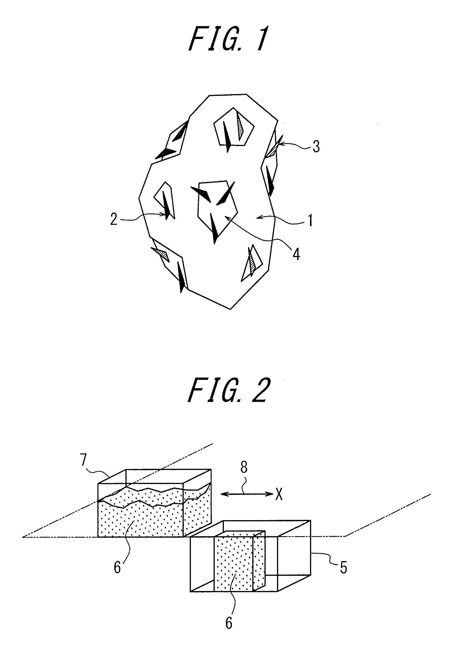
[0090]1: Iron powder[0091]2: Alloy component (graphite)[0092]3: Alloy component (copper powder)[0093]4: Binder[0094]5: Cavity[0095]6: Test iron powder[0096]7: Filling shoe[0097]8: Movement direction


PUM

PropertyMeasurementUnit
Fractionaaaaaaaaaa
Percent by massaaaaaaaaaa
Fractionaaaaaaaaaa

Abstract

An iron-based powder for powder metallurgy effectively prevents agglomeration of a lubricant, has excellent flowability, can evenly fill thin-walled cavities, keeps the ejection force after formation low, and does not lower sintered body strength by adhering either or both of an alloy component and a cutting ability improving agent to the surface of iron powder with a binder that has a melting point of 150° C. or lower, adhering carbon black to the surface of the binder, and setting the amount of free binder to 0.02 mass % or less.

Description

TECHNICAL FIELD[0001]The present invention relates to an iron-based powder that is suitable for use in powder metallurgy and that has an excellent ability to prevent segregation.BACKGROUND ART[0002]Powder metallurgical techniques allow for production of machine parts having complicated shapes with extremely high dimensional accuracy and are thus capable of significantly decreasing the production costs of such machine parts. Therefore, various machine parts produced by applying powder metallurgical techniques are used in many fields. Furthermore, in recent years, demand for miniaturization or reduced weight of machine parts has increased, and various precursor powders for powder metallurgy to produce small and lightweight machine parts having sufficient strength have been examined.[0003]JP H01-219101 A (PTL 1), JP H02-217403 A (PTL 2), and JP H03-162502 A (PTL 3), for example, disclose precursor powders for powder metallurgy produced by adhering an alloying powder to surfaces of iron...

Claims


Application Information

Patent Timeline
IPC IPC(8): B22F1/00B22F1/02B22F1/05B22F1/10B22F1/102B22F1/16B22F1/17
CPCB22F1/0059Y10T428/2991B22F1/02C22C33/0207B22F1/05B22F1/102B22F1/16B22F1/17B22F1/10B22F1/108
Inventor ONO, TOMOSHIGEOZAKI, YUKIKOKAWANO, TAKASHI
Owner JFE STEEL CORP
Why Eureka
Try Eureka