Gamma-Ray Spectrometry

Active Publication Date: 2015-11-05
SYMETRICA
View PDF16 Cites 9 Cited by
  • Summary
  • Abstract
  • Description
  • Claims
  • Application Information

AI Technical Summary

Benefits of technology

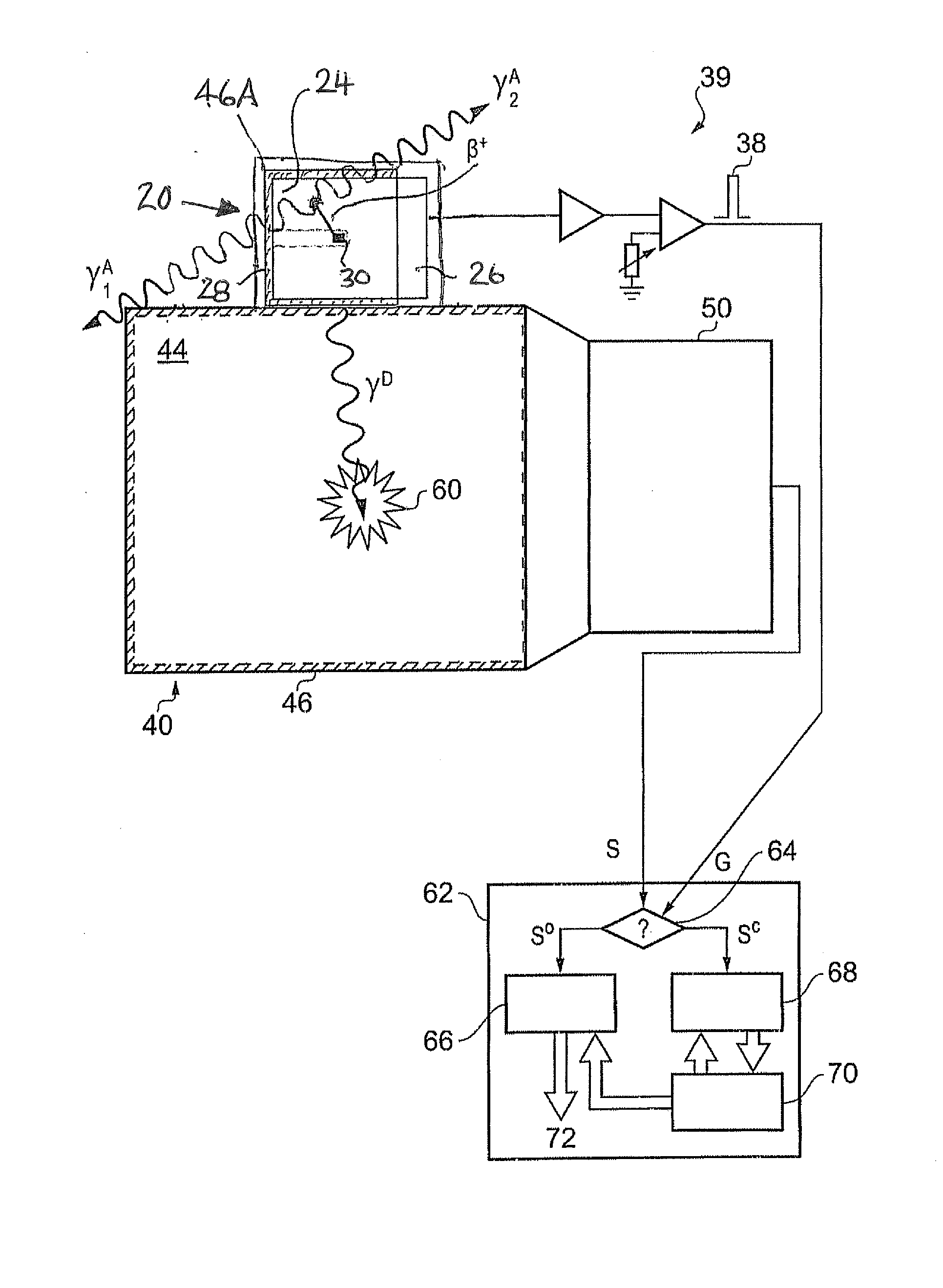
[0035]The radiation particle may be a beta particle, for example a beta-plus particle (positron). A positron has the advantage of further producing two 511 keV annihilation gamma-rays which may also be detected by an associated gamma-ray spectrometer and used as calibration points for monitoring the spectrometer's response. In principle the radiatio

Problems solved by technology

A problem with scintillator-based gamma-ray spectrometers is that the number of charge carriers Ncc generated at the photo-cathode of a PMT for a given gamma-ray energy deposit in a given spectrometer is not necessarily constant.
This is problematic because a failure to properly map output signals S back to energy deposits D will lead to a poorly calibrated spectrum, e.g. with peaks appearing at the wrong energies.
The problem of a spectrometer's response changing according to different conditions arises to some extent in all gamma-ray spectrometers, and not just in scintillator-based spectrometers.
If no account were taken of the change in environmental conditions, this output signal would be mapped back to an estimated energy deposit of between 0.8 and 0.9 MeV, and so result in an inaccurate energy-loss spectrum.
A problem with this approach is that it is difficult to monitor changes in environmental conditions, and to model their impact on a spectrometer's response, with high accuracy.
This approach can result in relatively bulky spectrometers

Method used


Image

  • Gamma-Ray Spectrometry
  • Gamma-Ray Spectrometry
  • Gamma-Ray Spectrometry

Examples


Embodiment Construction

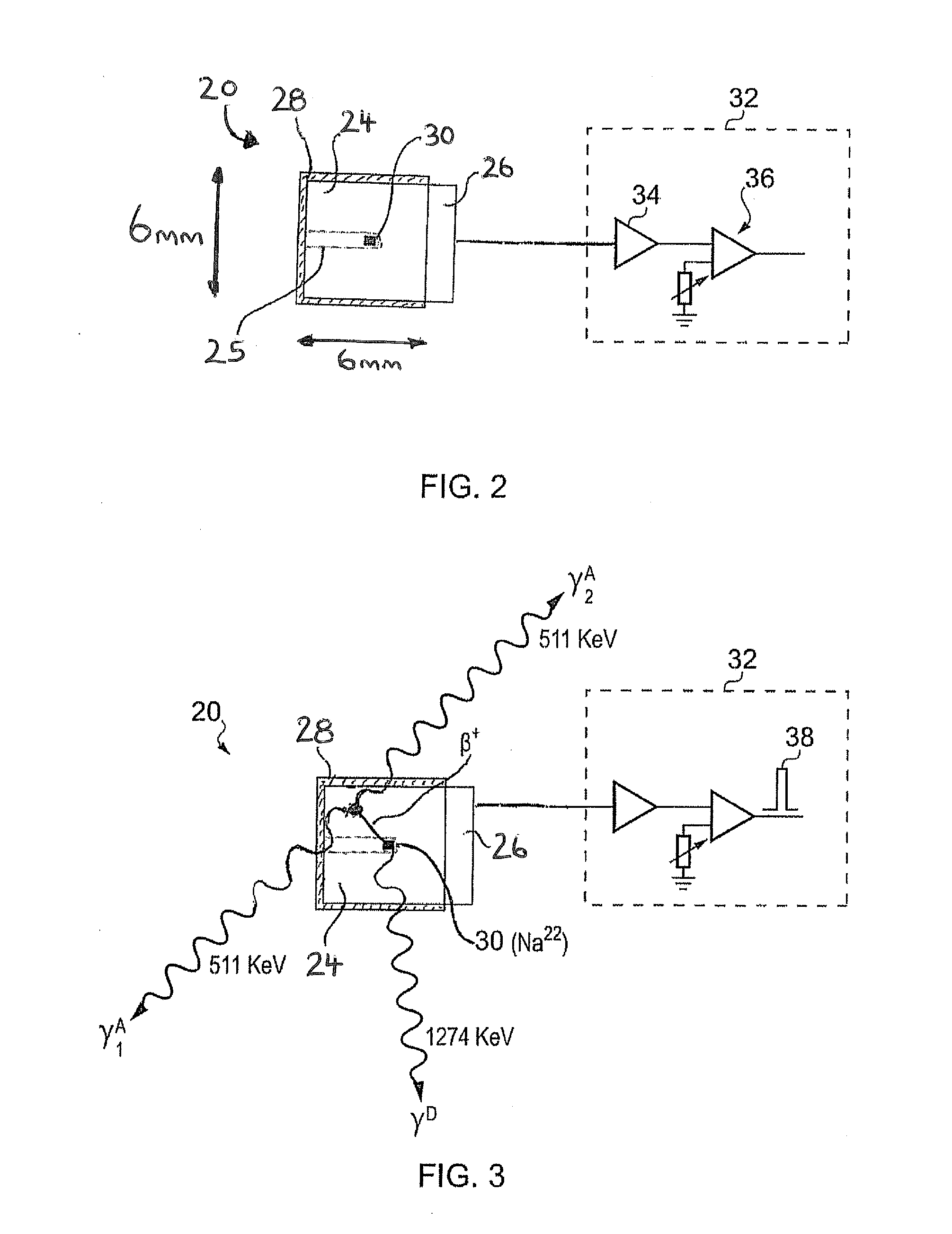
[0047]FIG. 2 schematically shows a calibration source 20 according to an embodiment of the invention. The calibration source 20 is based around a deposit of radioactive material 30 comprising a radioactive isotope having a decay transition associated with emission of a radiation particle and a gamma-ray. In this example, the radioactive material comprises a salt of Na-22. Na-22 is associated with a radioactive transition that results in emission of a beta-plus particle (positron) having a maximum energy of around 545 keV, and a gamma-ray having an energy around 1274 keV. Subsequent matter-anti-matter annihilation of the positron further results in the emission of a pair of 511 keV gamma-rays. In this example the radioactive material 30 has an activity of around 100 Bq. This will of course reduce with time, with Na-22 having a half-life of around 2.6 years.

[0048]The calibration source 20 comprises a scintillator body 24, which in this example is generally cuboid with an extent of aro...


PUM


Abstract

A calibration source for a gamma-ray spectrometer is provided. The calibration source comprises a scintillator body having a cavity in which a radioactive material is received. The scintillator body may be generally cuboid and the cavity may be formed by a hole drilled into the scintillator body. The radioactive material comprises a radioactive isotope having a decay transition associated with emission of a radiation particle and a gamma-ray having a known energy e.g. Na-22. A photodetector, for example a silicon photomultiplier, is optically coupled to the scintillator body and arranged to detect scintillation photons generated when radiation particles emitted from the radioactive material interact with the surrounding scintillator bod. A gating circuit is arranged to receive detection signals from the photodetector and to generate corresponding gating signals for a data acquisition circuit of an associated gamma-ray spectrometer to indicate that gamma-ray detections in the gamma-ray spectrometer occurring within a time window defined by the gating signal are associated with a decay transition in the radioactive isotope. Thus a calibration source is provided based around a simple scintillator body design. Furthermore, the radioactive material may be introduced into the scintillator body in a separate step after manufacture of the scintillator body, thereby reducing the risk of radioactive contamination during manufacture.

Description

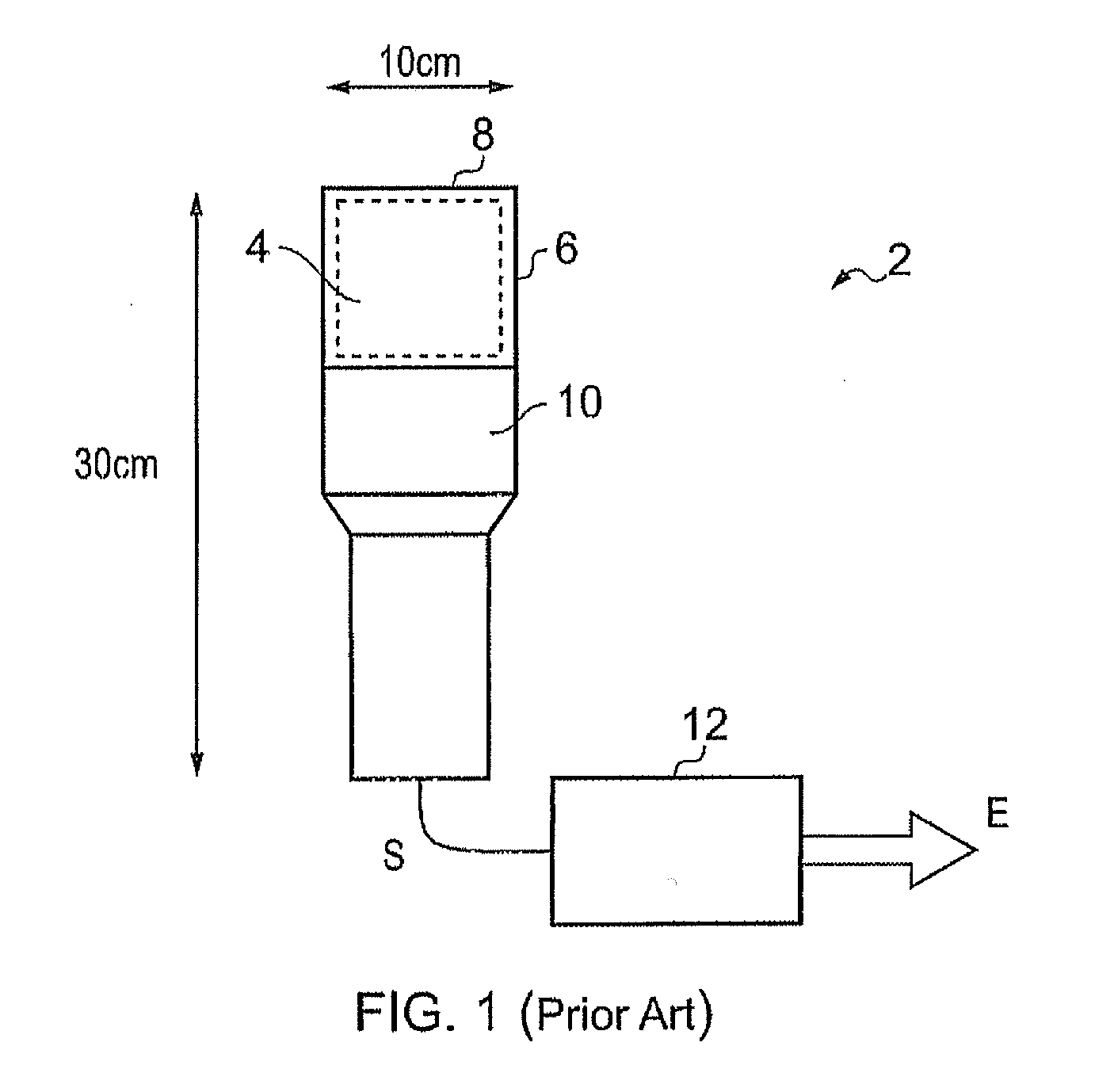
BACKGROUND ART[0001]The invention relates to gamma-ray spectrometry, and in particular to calibration sources for gamma-ray spectrometers and gamma-ray spectrometers having calibration sources.[0002]Gamma-ray spectrometers are used in a wide variety of applications, for example to identify and monitor gamma-ray sources in scientific, industrial, and environmental monitoring applications, e.g. for security screening of personnel and cargo at border crossings, or to search generally for orphaned radioactive sources. A common class of gamma-ray spectrometers is based on organic (plastic) or inorganic (crystal) scintillator materials.[0003]FIG. 1 shows an example of a conventional crystal scintillation spectrometer 2. The spectrometer is generally axially symmetric with a diameter of around 8 cm and a length of around 8 cm. The spectrometer 2 comprises a scintillation crystal 4 which scintillates when a gamma-ray is absorbed within it. A common scintillation crystal material is thallium...

Claims


Application Information

Patent Timeline
IPC IPC(8): G01T7/00G01T1/203G01T1/36G01T1/24
CPCG01T7/005G01T1/366G01T1/203G01T1/247G01T1/40G01T1/362
Inventor RAMSDEN, DAVID
Owner SYMETRICA
Why Eureka
Try Eureka