Fluidized bed boiler and method for enhancing furnace efficiency of the same

a fluidized bed boiler and furnace efficiency technology, applied in the field of boilers, can solve the problems of no or no/sub>2/sub> in the flue gas after combustion, hazardous to the central nervous system, cerebral palsy (cp), limb atrophy, etc., and achieve the effect of reducing the oxygen content of the flue gas and nitrogen oxide emission, and enhancing the furnace efficiency of the fluidized bed boiler

Inactive Publication Date: 2015-11-19
CHUNG YUAN CHRISTIAN UNIVERSITY
View PDF0 Cites 8 Cited by
  • Summary
  • Abstract
  • Description
  • Claims
  • Application Information

AI Technical Summary

Benefits of technology

[0007]A method for enhancing furnace efficiency of a fluidized bed boiler is provided. The method takes advantage of recirculation of a portion of a flue gas to reduce oxygen content in the flue gas and nitrogen oxide emission.
[0008]An aspect of the present disclosure provides a method for enhancing furnace efficiency of a fluidized bed boiler. The fluidized bed boiler includes a boiler body, a fluidized gas inlet, a steam outlet and a flue-gas exhaust. The boiler body carries out fuel combustion in a fluidized bed of the boiler body. The fluidized gas inlet inputs an oxygen-containing fluidized gas or a feeding fluidized gas into the boiler body to fluidize a boiler bed to form the fluidized bed and facilitate the fuel combustion. The steam outlet outputs a steam resulting from the fuel combustion from the boiler body. The flue-gas exhaust emits a flue gas resulting from the fuel combustion from the boiler body. The method includes steps of: detecting an oxygen concentration of the flue gas; feeding a portion of the flue gas back to the fluidized gas inlet to provide a recirculating flue gas which is mixed with the feeding fluidized gas to form the oxygen-containing fluidized gas; and dynamically adjusting a flow rate of the feeding fluidized gas according to the detected oxygen concentration of the flue gas and an oxygen concentration of the feedi...

Problems solved by technology

Furthermore, nitrogen oxides (NOx, e.g. NO or NO2) in the flue gases after the combustion are hazardous to central ...

Method used


Image

  • Fluidized bed boiler and method for enhancing furnace efficiency of the same
  • Fluidized bed boiler and method for enhancing furnace efficiency of the same
  • Fluidized bed boiler and method for enhancing furnace efficiency of the same

Examples


Embodiment Construction

[0016]The present disclosure will now be described more specifically with reference to the following embodiments. It is to be noted that the following descriptions of preferred embodiments of this invention are presented herein for purpose of illustration and description only. It is not intended to be exhaustive or to be limited to the precise form disclosed.

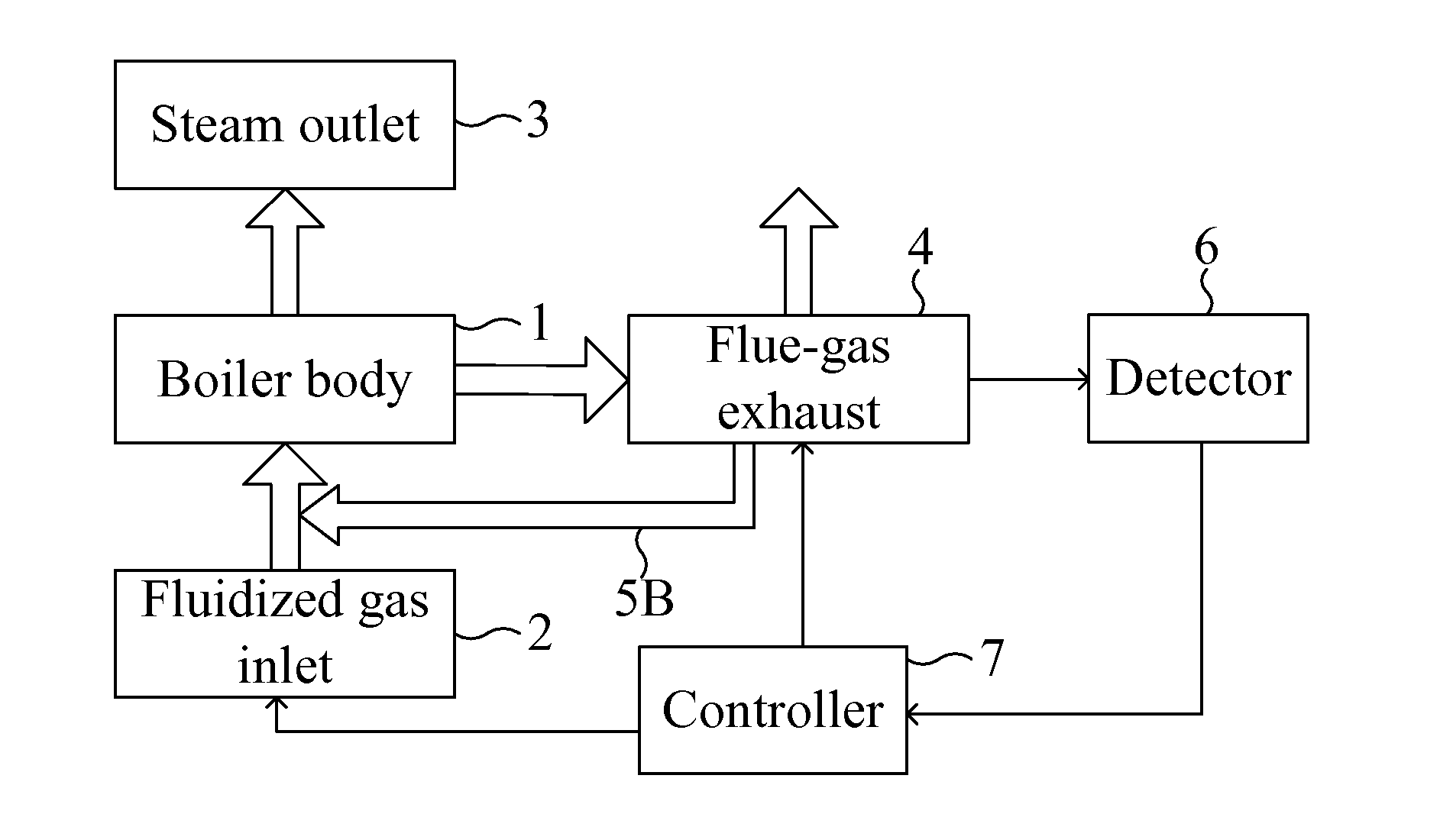
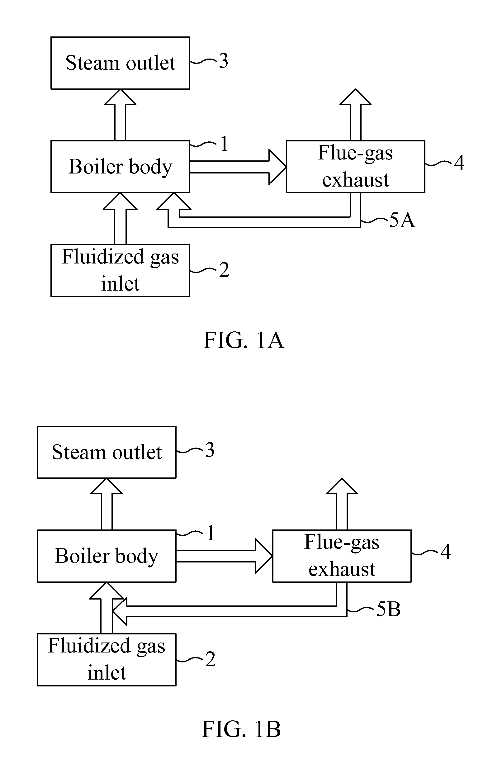
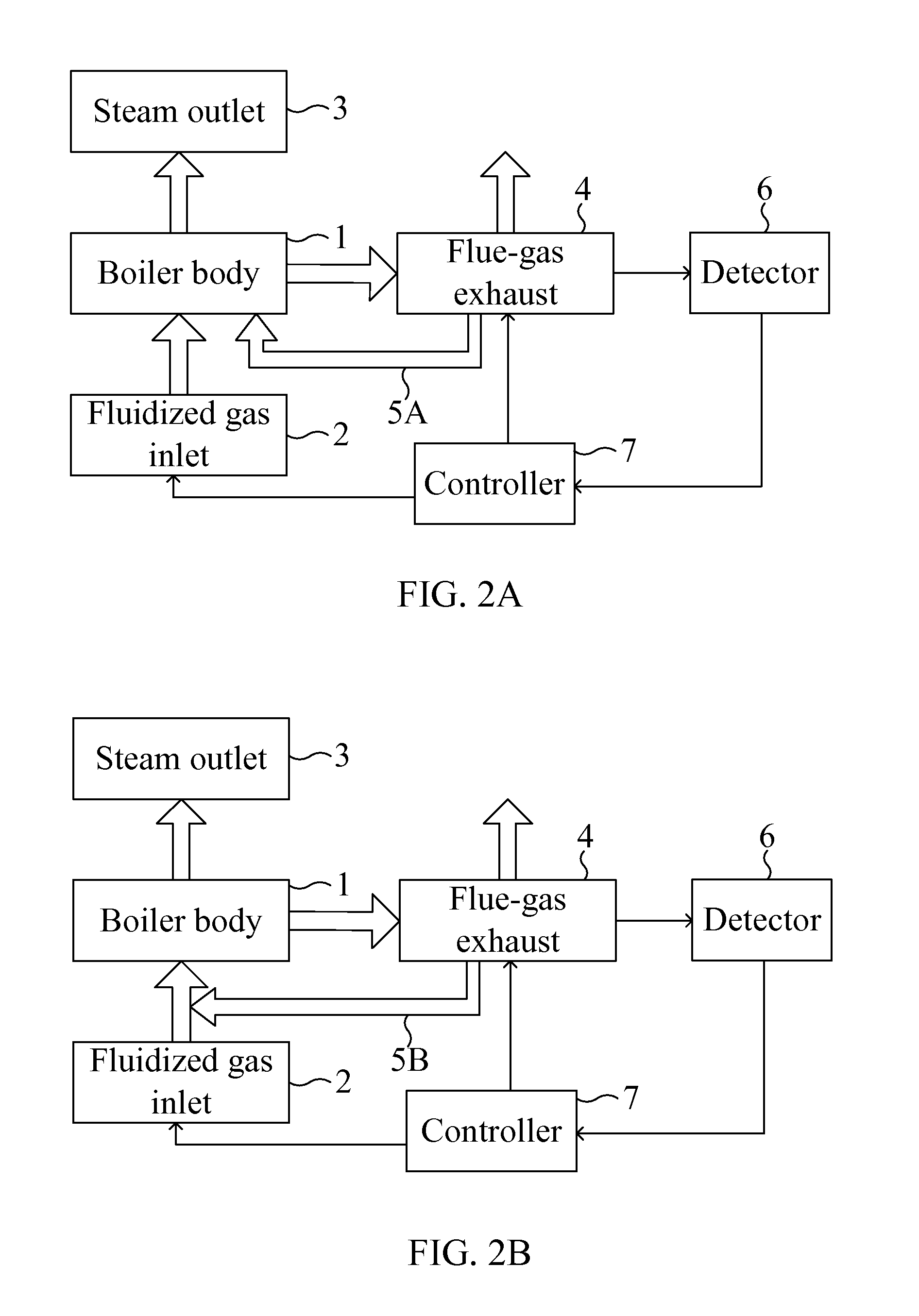
[0017]In order to overcome the problem of high oxygen content in a flue gas and high nitrogen oxide emission, a portion of the flue gas is fed back for recirculation and mixed with a feeding fluidized gas to maintain a gas flow rate in the fluidized bed boiler. By this way, oxygen supply is lowered so that the oxygen content in the flue gas decreases. In addition, the recirculation of the flue gas also decreases nitrogen oxide emission.

[0018]Concretely, the method for enhancing furnace efficiency of the fluidized bed boiler involves replacing a portion of primary air with the recirculating flue gas. The ratio of the recirculatin...


PUM


Abstract

A method for enhancing furnace efficiency of a fluidized bed boiler is provided. The fluidized bed boiler includes a boiler body for carrying out fuel combustion in a fluidized bed thereof; a fluidized gas inlet for inputting an oxygen-containing fluidized gas into the boiler body to fluidize a boiler bed and facilitate the fuel combustion; a steam outlet for outputting a steam resulting from the fuel combustion from the boiler body; and a flue-gas exhaust for emitting a flue gas resulting from the fuel combustion from the boiler body. The method includes steps of: detecting an oxygen concentration of the flue gas; feeding a portion of the flue gas back to the fluidized gas inlet; and dynamically adjusting a flow rate of the feeding fluidized gas according to oxygen concentrations of the flue gas and the feeding fluidized gas to achieve automatic control of the fluidized bed boiler.

Description

FIELD OF THE INVENTION[0001]The present disclosure relates to a boiler, and particularly to a fluidized bed boiler. The present disclosure also relates to a method for enhancing furnace efficiency of the fluidized bed boiler.BACKGROUND OF THE INVENTION[0002]A boiler is a closed vessel in which water or other fluid is heated by fuel combustion and converted into vapor. By means of the boiler, chemical energy of fuel is transformed into thermal energy for various heating applications. As known, combustion efficiency is determined by 3T—temperature, time and turbulence, which respectively represent temperature in the boiler, retention time of the fuel and turbulence of mixing fuel and air / oxygen. A fluidized bed boiler has the advantage of high turbulence.[0003]In recent years, bubbling fluidized bed boilers and circulating fluidized bed boilers are the most used fluidized bed boilers. In a bubbling fluidized bed boiler, air jets are provided from the bottom thereof, and heat pipes are...

Claims


Application Information

Patent Timeline
IPC IPC(8): F23C10/28F23C9/00F23C10/18
CPCF23C10/28F23C9/00F23C10/18F22B31/0007F23N1/022F23N5/006F23N2241/10Y02E20/34
Inventor CHYANG, CHIEN-SONG
Owner CHUNG YUAN CHRISTIAN UNIVERSITY
Why Eureka
Try Eureka