Magnetic drive type air charging device

a charging device and magnetic drive technology, applied in the direction of positive displacement liquid engines, piston pumps, liquid fuel engines, etc., can solve the problems of increasing cost, unable to obtain desired boost, and limit the output of increasing, so as to shorten the spooling time, increase the volumetric efficiency of internal combustion engines, and increase the air density and flow rate

Active Publication Date: 2015-12-17
HAN SEUNGJOO
View PDF2 Cites 9 Cited by
  • Summary
  • Abstract
  • Description
  • Claims
  • Application Information

AI Technical Summary

Benefits of technology

[0021]The present invention provides an air charging apparatus. Here, air volume flow corresponding to the characteristics of the internal combustion engine and the vehicle having durability to supercharging is supplied to increase the volumetric efficiency of the internal combustion engine by being mounted between an air filter and an inlet pipe of the internal combustion engine to compressing or pressurizing air and thus increase the air density and flow rate. In a low-speed driving region and transient section, the torque is increased to shorten the spool-up time and thus improve the response characteristic of a vehicle. In order to increase a deficient super pressure supplied by an existing supercharger in a low-speed region, the fuel consumption of the internal combustion engine is reduced. Also, the load of the internal combustion engine operated in order to maintain the super pressure at a high level in a high-speed driving region is reduced. Thus, the air supply device corresponding to the internal combustion engine having high specific power according to the carbon emission regulation and the downsizing trend of a vehicle is achieved. Without giving a load to a vehicle and an internal combustion engine, the temperature of supplied air becomes lower and the air density becomes relatively higher compared to an existing supercharger. In such air supply device, the driving loss and driving noise become lower, and the durability becomes better. Also, the air supply device uses low power or does not need the driving cost, and can be easily installed without limitations of a specific location and a mounting direction.

Problems solved by technology

However, since air volume flow inhaled into a combustion chamber in intake stroke is not sufficient due to air intake resistance compared to actual displacement volume, there is a limitation in increasing the output.
However, the supercharging vehicle equipped with the turbocharger acquires sufficient super pressure in a high-speed driving region, but cannot obtain desired boost due to efficiency reduction caused by low exhaust gas energy in a low-speed driving region.
However, in these complex supercharging devices, the increase of the number of parts, the complication of the structure, the addition of a control system cause the increase of cost.
Also, in case of an internal combustion engine ignited at an air-fuel ratio like gasoline fuel, when a supercharging device is applied, due to supercharged air increase in temperature, knocking easily occurs from the compression ratio of the internal combustion engine.
Accordingly, the super pressure is difficult to increase to a certain level.
On the other hand, when the super pressure is supplied at a low level, it is difficult to expect the increase of the output, and when the compression ratio of the internal combustion engine is lowered and the super pressure is increased, a high output can be obtained in the whole load, but the fuel efficiency is reduced in a partial load.
Also, in the supercharging internal combustion engine equipped with the turbocharger and the supercharger, fuel is additionally consumed to drive the supercharger and generate compressed air in addition to fuel consumption necessary for improvement of volumetric efficiency.
Also, since the turbocharger is mounted on the side of the outlet of the exhaust manifold and the supercharger needs to be aligned with a belt connected to the crankshaft supplying the power, the location and the direction of the mounting space are restricted, complicating the arrangement of parts of the internal combustion engine.
Since the superchargers receive power of the internal combustion engine to perform necessary operations by controllers of components, air volume flow could not be controlled and supplied corresponding to the characteristics of the internal combustion engine and the vehicle.
Also, in the natural aspirated vehicle and motor cycle, since air is not charged corresponding to actual displacement volume due to the air intake resistance, there is a limitation in increasing the output.
However, since the electric air compressor uses power produced in the fuel cell or battery charged power, the capacity and the volume of the fuel cell and the battery become larger, inevitably affecting the travelling distance of a vehicle.

Method used


Image

  • Magnetic drive type air charging device
  • Magnetic drive type air charging device
  • Magnetic drive type air charging device

Examples


first embodiment

[0156]Hereinafter, components, and combination structures, actions and operations thereof will be described.

[0157]First, the components will be described with reference to the accompanying drawings.

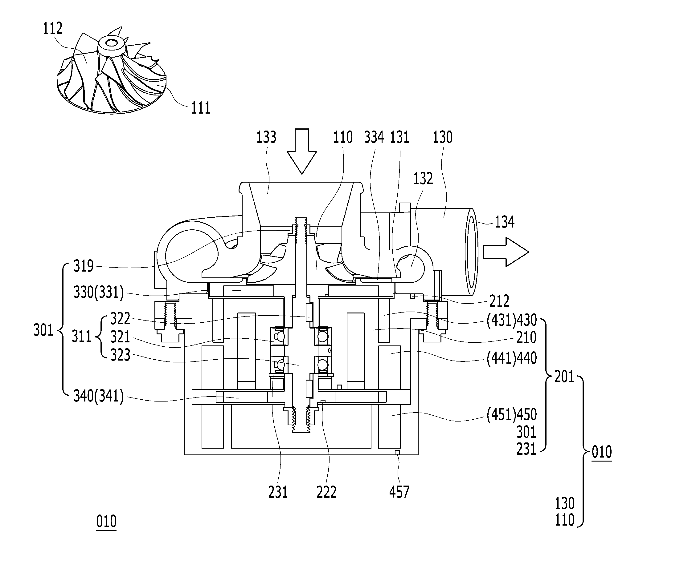
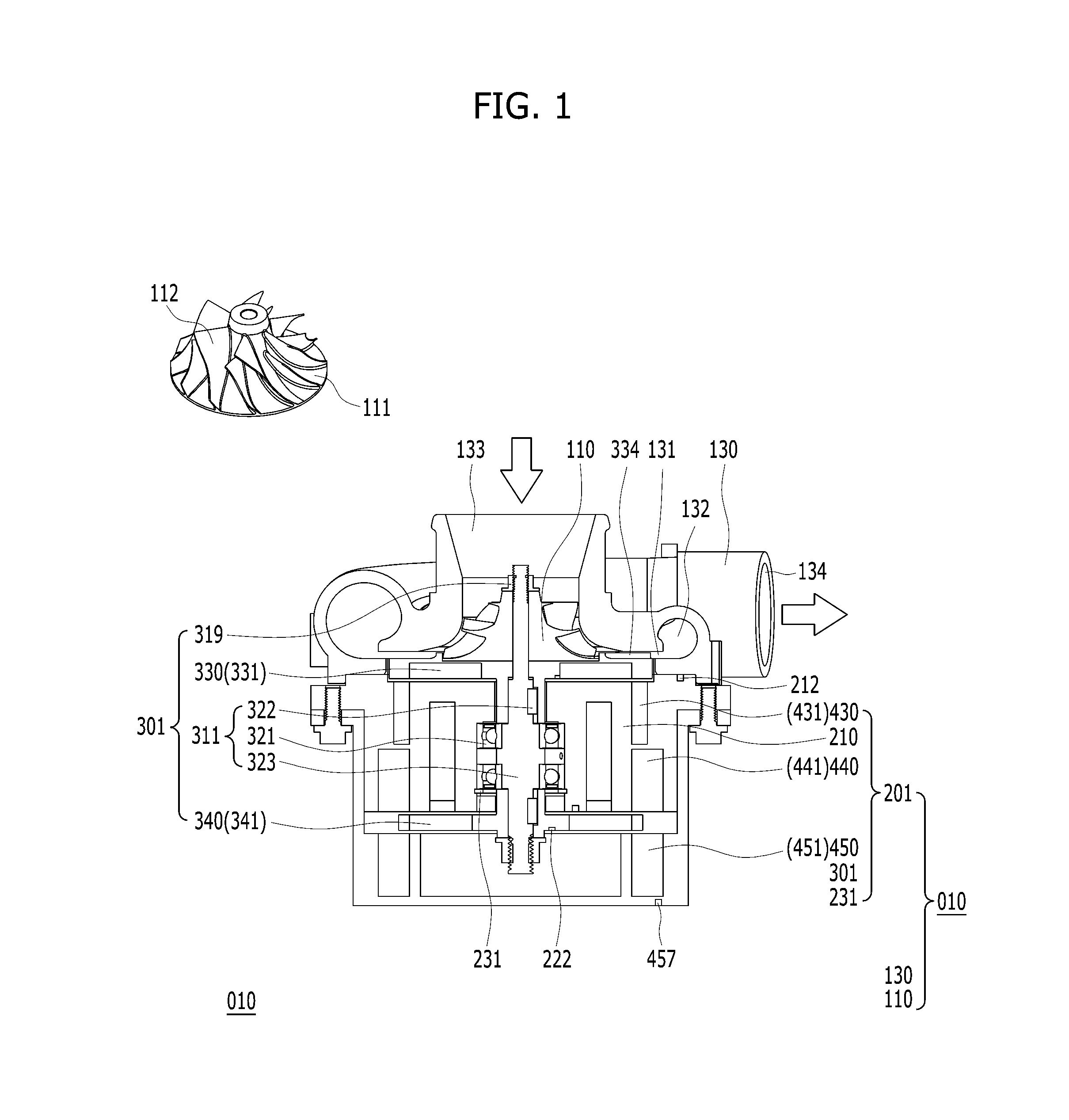
[0158]As shown in FIGS. 1 and 22, an air charging apparatus 010 of compressing or pressurizing and transferring air may include an impeller 110 sucking air and giving kinetic energy to intake air, an impeller case 130 leading external air inhaled by the impeller 110 into the impeller 110 and converting velocity energy of air out of the impeller 110 into pressure energy to discharge air, and a rotating body accelerator 201 equipped with the impeller 110 and the impeller case and driving the impeller 110. Hereinafter, each component will be described in detail.

[0159]As shown in FIGS. 1, 22, and 23, the rotating body accelerator 201 may be equipped with a complex rotating body 301 in a frame 210. The magnetic flux of the complex rotating body 301 may be disposed in the axial direction of th...

second embodiment

[0214]Hereinafter, components, and combination structures, actions and operations thereof will be described.

[0215]First, the components will be described with reference to the accompanying drawings.

[0216]Compared to the first embodiment, a rotating body accelerator 202 according to the second embodiment of the present invention 020 may include an upper rear driver 460 including permanents magnets and coils or coils. The upper rear driver 460 may include an upper fixing support 465 having a cylindrical body, one side surface of which is closed and the inner circumferential surface and the outer circumferential surface of which have permanent magnet and coil holes 466 formed at a uniform interval in alignment with a reference point 467 in a circumferential axial direction and circumferential axial diameter direction around the rear rotator 340. The upper fixing support 465 may include a protrusion on the outer circumferential surface of the body to form bolt holes 468 for fixing to t...

third embodiment

[0230]Hereinafter, components, and combination structures, actions and operations thereof will be described.

[0231]First, the components will be described with reference to the accompanying drawings.

[0232]Compared to the first embodiment, as shown in FIGS. 13 to 15, and 23, in a rotating body accelerator 203 according to the third embodiment 030 of the present invention, the direction of the magnetic flux of the complex rotating body 301 may include a rear rotator 350 of a complex rotating body 303, the magnetic flux of which is disposed toward an axial diameter direction of the frame 210, and a lower rear driver 490 and an upper rear driver 470, the magnetic fluxes of which are disposed toward an axial direction of the frame 210, instead of the rear rotator 340 of the complex rotating body 301, the magnetic flux of which is disposed toward an axial direction of the frame 210, and the lower rear driver 440 and the upper rear driver 450, the magnetic fluxes of which are disposed towa...


PUM


Abstract

Provided is an air charging apparatus driven by a rotating magnetic field and compressing or pressurizing and transferring air. The air charging apparatus includes at least one impeller sucking air and giving kinetic energy to intake air; an impeller case leading external air inhaled by the impeller into the impeller and converting velocity energy of air out of the impeller into air having pressure energy to discharge air; and a rotating body accelerator equipped with the impeller and the impeller case and driving the impeller. Here, the rotating body accelerator drives the impeller by generating a torque by interaction with an intake negative pressure, by generating a torque by interaction with the intake negative pressure and using supplied power, or by generating a torque using supplied power.

Description

BACKGROUND OF THE INVENTION[0001]The present invention disclosed herein relates to an air charging apparatus driven by a rotating magnetic field, which increases the volumetric efficiency of an internal combustion engine and compressing and pressurizing air in order to supply compressed or pressurized air to a fuel cell vehicle.[0002]Various driving types of air supply devices are being used to increase the volumetric efficiency of an internal combustion engine and thus improve the output of the internal combustion engine and the acceleration performance of a vehicle.[0003]Compared to a supercharging vehicle including a supercharging device which compresses and transfers intake air using power of the internal combustion engine, a motor cycle and a natural aspirated vehicle mounted with an natural aspiration internal combustion engine which inhales air using an intake negative pressure and a pressure difference of the atmospheric pressure are low in load failure rate of the internal ...

Claims


Application Information

Patent Timeline
Patent Type & Authority Applications(United States)
IPC IPC(8): F02B33/40F04D29/42F04D29/28F04D29/70F04D17/10F04D25/06
CPCF02B33/40F04D17/10F04D29/4206F04D29/284F04D29/701F04D25/06F02B37/10F02B39/10F04D25/0653F05D2220/40F02B33/34F02B39/00
Inventor HAN, SEUNGJOO
Owner HAN SEUNGJOO
Why Eureka
Try Eureka