
Low cost spinning and fabrication of high efficiency (HE) haemodialysis fibers and method thereof

a technology of haemodialysis fibers and low cost, which is applied in the field of apparatus and method to spin hollow fibres of dialysis grade, can solve the problem of final cost of cartridges, and achieve the effect of convenient manufacturing

Inactive Publication Date: 2016-01-14
INDIAN INSTITUTE OF TECHNOLOGYKHARAGPUR
View PDF2 Cites 11 Cited by
  • Summary
  • Abstract
  • Description
  • Claims
  • Application Information

AI Technical Summary

Benefits of technology

The present invention proposes a new method to spin dialysis grade hollow fibres using a simple needle assembly. This method is cost-effective and requires no electrical power, making the fibres easy to manufacture and afford at the consumer end. The use of cheaply assembled syringes (dispo van and insulin syringes) allows for the efficient production of these fibres. Overall, this invention provides a new design for spinning hollow fibres that are both cost-effective and easy to manufacture.

Problems solved by technology

This makes them expensive and final cost of the cartridge is in the range of Rs.
Due to economic constraints, majority of the people are unable to use 3 cartridges per week, resulting to two-three reuses of the same cartridge.

Method used


Image

  • Low cost spinning and fabrication of high efficiency (HE) haemodialysis fibers and method thereof
  • Low cost spinning and fabrication of high efficiency (HE) haemodialysis fibers and method thereof
  • Low cost spinning and fabrication of high efficiency (HE) haemodialysis fibers and method thereof

Examples


example 1

[0045]In the present example, the water permeability is measured by using pure distilled water at various transmembrane pressure drops. The permeate flux is measured at various transmembrane pressure drops and flux versus pressure drop data are plotted. This results into a straight line through origin as pure distilled water does not have any osmotic pressure. The slope of this curve gives the value of membrane permeability. It indicates how porous the hollow fiber is. This is represented in FIG. 5A.

example 2

[0046]In this present example, experiments are conducted using various solutes, like, polyethylene glycol of various molecular weights (400 to 35,000), dextran (70,000), etc., at 1,000 ppm and at about 12 kPa pressure and 20 l / h cross flow rate. The rejection values were measured by using the following formula:

R=(1-cpc0)×100%(1)

[0047]FIG. 5B represents the data. It is observed that the 90% rejection of solutes occur at around 6000 Da (6 kDa), hence by definition, this is the MWCO of the spun membrane.

[0048]In fact, varying the wt. % of PVP, a variety of membranes of the specified dialysis grade can be spun, the details are given in Table 2.

TABLE 2Range of Molecular Weight Cut Off (MWCO)Sl. NoPVP wt. %PEG wt. %MWCO1136223143331743044

example 3

[0049]In this example, the diffusive permeabilities (PD) values of the membrane is calculated. It is calculated as:

PD={lnΔC1(t1)ΔC2(t2)}S{1Va+1Vb}(t2-t1)(2)

where, ΔC(t) is the difference between the solute concentrations in the solutes and dialysate reservoirs at the sampling time, t1 and t2, V is the reservoir volume; S is the surface area of the membrane, t is the time

[0050]The experiments are conducted in usual dialysis mode and the PD values obtained are reported in the following table:

TABLE 3Diffusive permeabilties of the membranePolymer Blend MembraneReported ValuesComponents(×10−4), cm / s(×10−4), cm / sUrea14.115.2Creatinine7.48.8Sucrose1.92.4Vitamin B120.220.25BSA00


PUM

PropertyMeasurementUnit
angleaaaaaaaaaa
diameteraaaaaaaaaa
diameteraaaaaaaaaa

Abstract

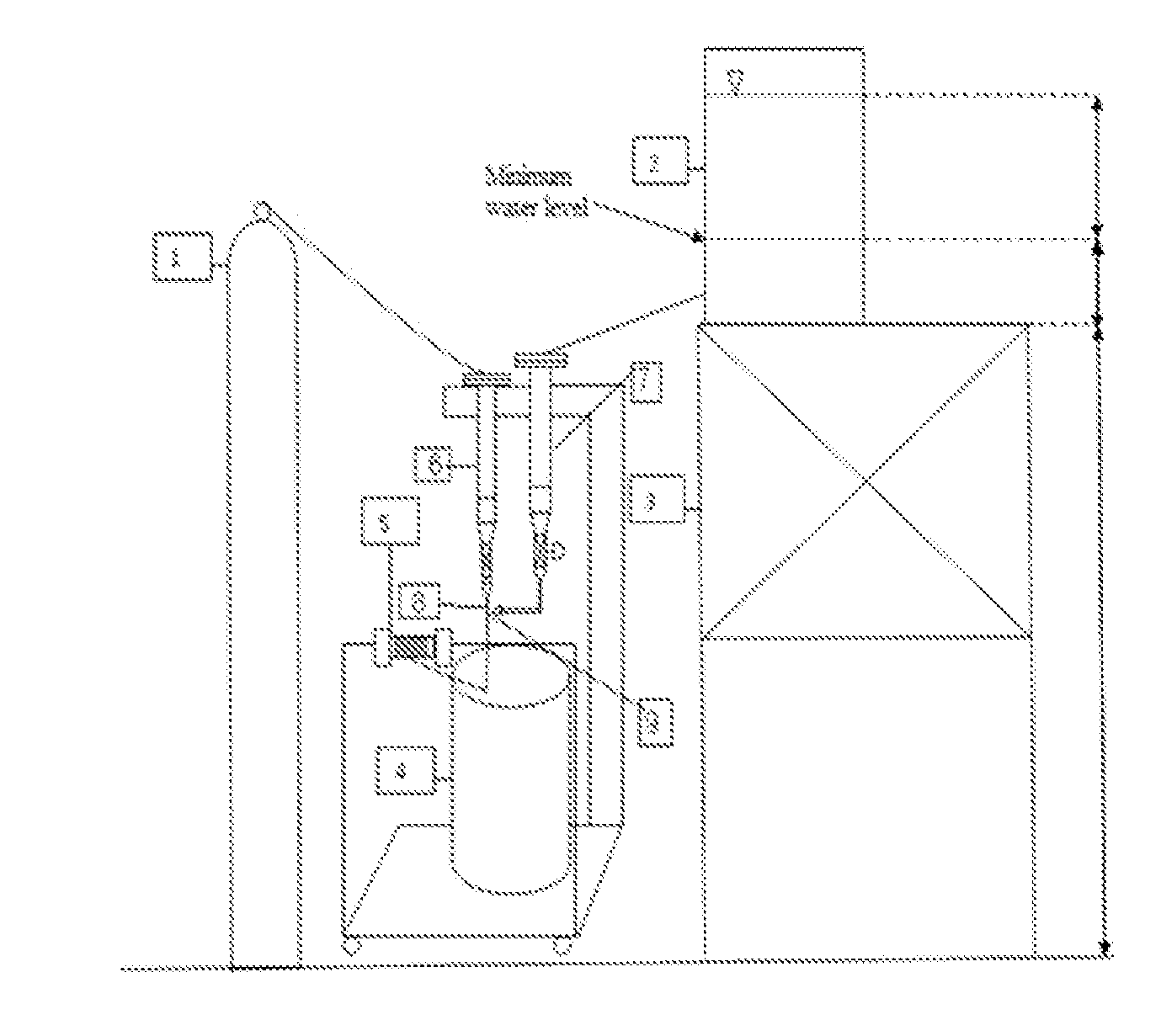
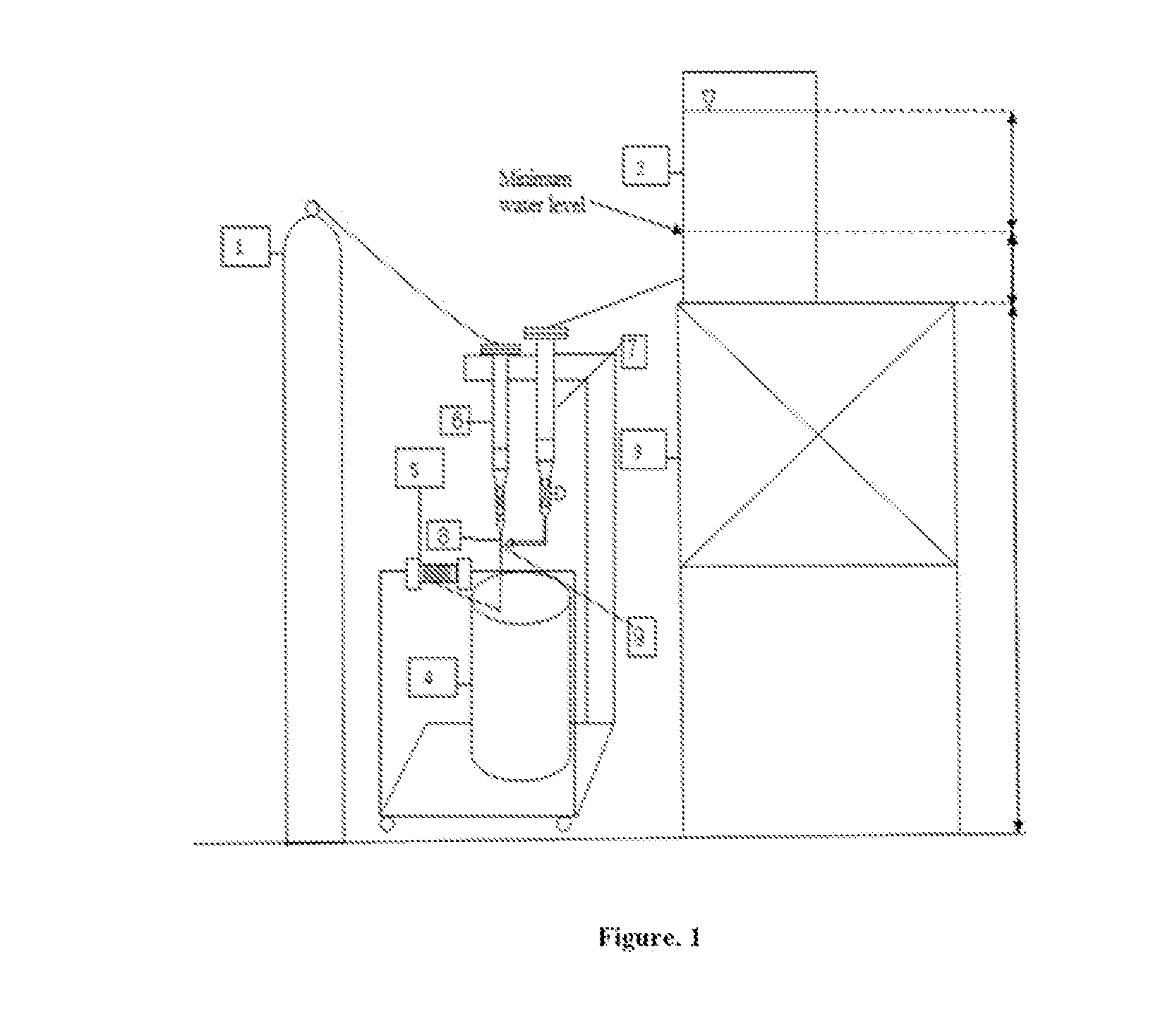
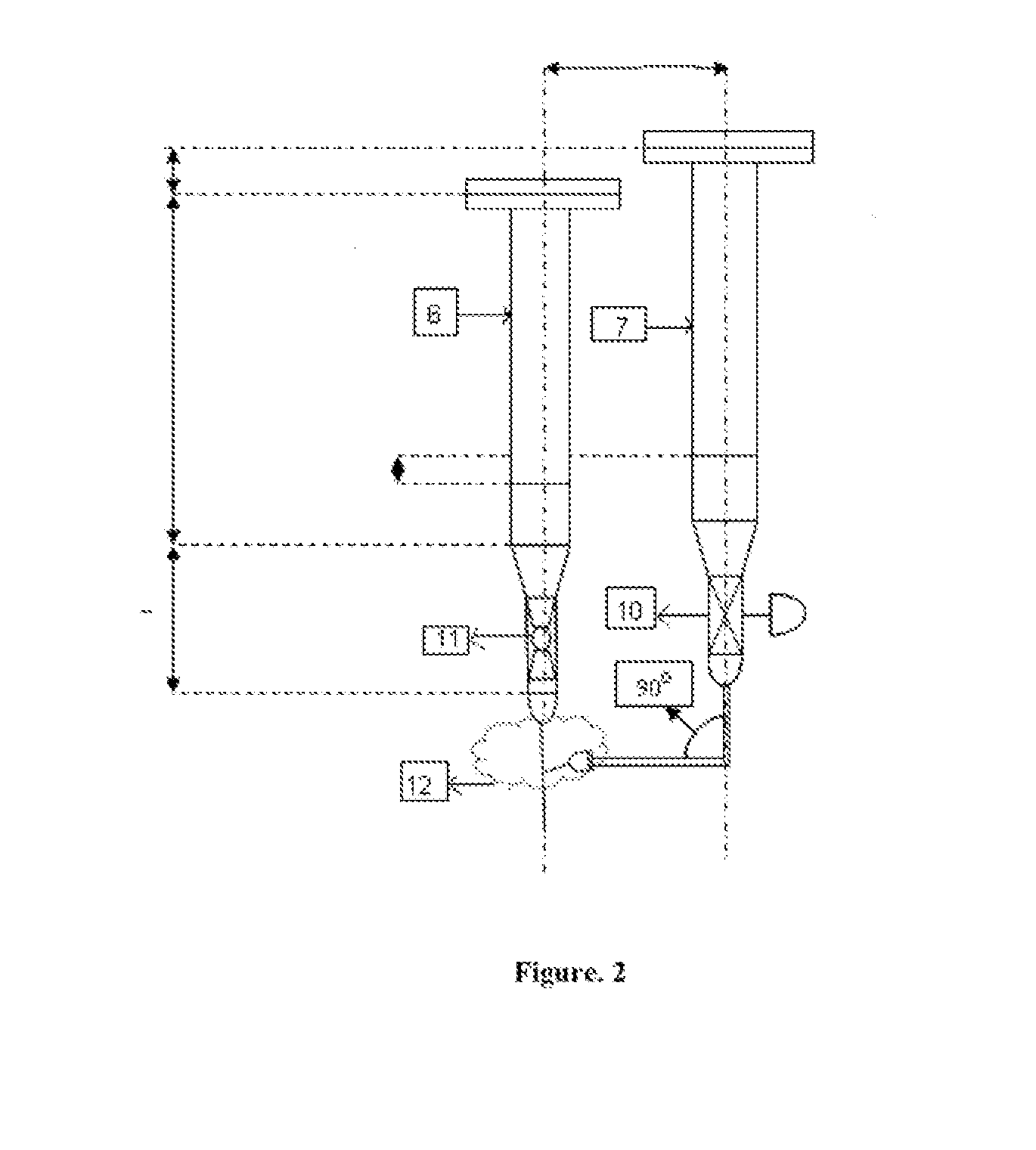
The present invention relates to an apparatus and a method to spin hollow fibres of dialysis grade with diameter around 220 microns and thickness of around 35-40 microns, by wet spinning technique. The present invention spinning is carried out by using an apparatus having a nitrogen cylinder (1), water bucket (2), polymer cylinder (6), water cylinder (7), automatic winding machine (5) characterized by a cheap assembly of syringes (dispo van (8) and insulin syringes (9)) wherein no electrical power is required for the spinning, making the fibres extremely easy to manufacture and affordable at the consumer end.

Description

FIELD OF THE INVENTION[0001]The present invention relates to an apparatus and method to spin hollow fibres of dialysis grade. More particularly, the present invention relates to spin hollow fibres of dialysis grade with diameter around 220 microns and thickness of around 35-40 microns, by wet spinning technique.BACKGROUND OF THE INVENTION[0002]Typically, patients suffering from end stage renal disease (ESRD) are administered treatment through dialysis. Dialysis is of two types: (i) Peritoneal dialysis, and (ii) Hemodialysis. In India, hemodialysis is carried out using dialysis cartridges, which are imported from Japan, Germany and Korea, since the expertise of manufacturing these is not presently available. The crux of the problem lies in spinning of hollow fibers, of specific dimensions, and potting them in a casing. Typically, individual such hollow fibres would measure around 180-220 microns in diameter, with wall thickness of around 15-35 microns. Around 7000-15000 of such indiv...

Claims


Application Information

Patent Timeline
Patent Type & Authority Applications(United States)
IPC IPC(8): A61M1/16B29C48/05B29C48/09D01D5/06D01D5/38
CPCA61M1/1623D01D5/06D01D5/38B29C47/0023A61M2207/10B29L2031/7546B29L2023/22A61M2207/00B29C47/0014B01D69/08D01D5/24D01D5/247B01D2323/42B29C48/05B29C48/09
Inventor ROY, ANIRBANDE, SIRSHENDUVINCENT, LLOYDRAO, SHYAM VASUDEVA
Owner INDIAN INSTITUTE OF TECHNOLOGYKHARAGPUR
Learn More