Solid state image sensor, manufacturing method thereof, and electronic device

a solid-state image sensor and manufacturing method technology, applied in the direction of diodes, semiconductor devices, radiation control devices, etc., can solve the problems of limiting the shutter speed, difficult to reduce the size, distortion generated on the subject image, etc., and achieve the effect of high conversion efficiency of photoelectric conversion

Active Publication Date: 2016-01-21
SONY SEMICON SOLUTIONS CORP
View PDF7 Cites 36 Cited by
  • Summary
  • Abstract
  • Description
  • Claims
  • Application Information

AI Technical Summary

Benefits of technology

[0042]According to the first to third aspect of the present technology, a solid state image sensor that is tolerant to misalignment during manufacturing and having a high conversion efficiency of photoelectric conversion is configured.

Problems solved by technology

In this CMOS solid state image sensor, an electric charge accumulated in each pixel or each row of photo diode is read, and thus a difference occurs between the time periods during which optical charges are accumulated, which results in a distortion generated on an imaged subject when the subject is moving.
However, in the mechanical shutter method, the mechanical shutter is necessary, and thus reduction in size is difficult, and mechanical drive limits the shutter speed.
Also, the electric charge accumulating parts and a pixel circuit unit are arranged close to the front side of the semiconductor substrate, there is a problem that the photo diode has a low aperture ratio.
However, in the technology disclosed in Patent Literature 4, the photo diode is arranged on a top layer surface (surface) of the back side of the semiconductor substrate, and thus the photo diode area is difficult to be arranged.

Method used


Image

  • Solid state image sensor, manufacturing method thereof, and electronic device
  • Solid state image sensor, manufacturing method thereof, and electronic device
  • Solid state image sensor, manufacturing method thereof, and electronic device

Examples


Embodiment Construction

[0084]In the following, embodiments for carrying out the present technology (hereinafter, referred to as embodiment) will be described. Note that, description will be made in the following order.

1. An overall configuration example of a solid state image sensor employing the present technology

2. First to sixth configurations of a pixel of a solid state image sensor

3. A manufacturing method of a pixel of the third configuration

4. Seventh to thirteenth configurations of a pixel of a solid state image sensor

5. A manufacturing method of a pixel of the seventh configuration

6. A manufacturing method of a pixel of the tenth configuration

7. An exemplary configuration of an electronic device employing the present technology

[0085]FIG. 3 is a block diagram illustrating an overall configuration example of a solid state image sensor employing the present technology.

[0086]The solid state image sensor 41 of FIG. 3 includes a timing control unit 42, a vertical scanning circuit 43, a pixel array unit...


PUM


Abstract

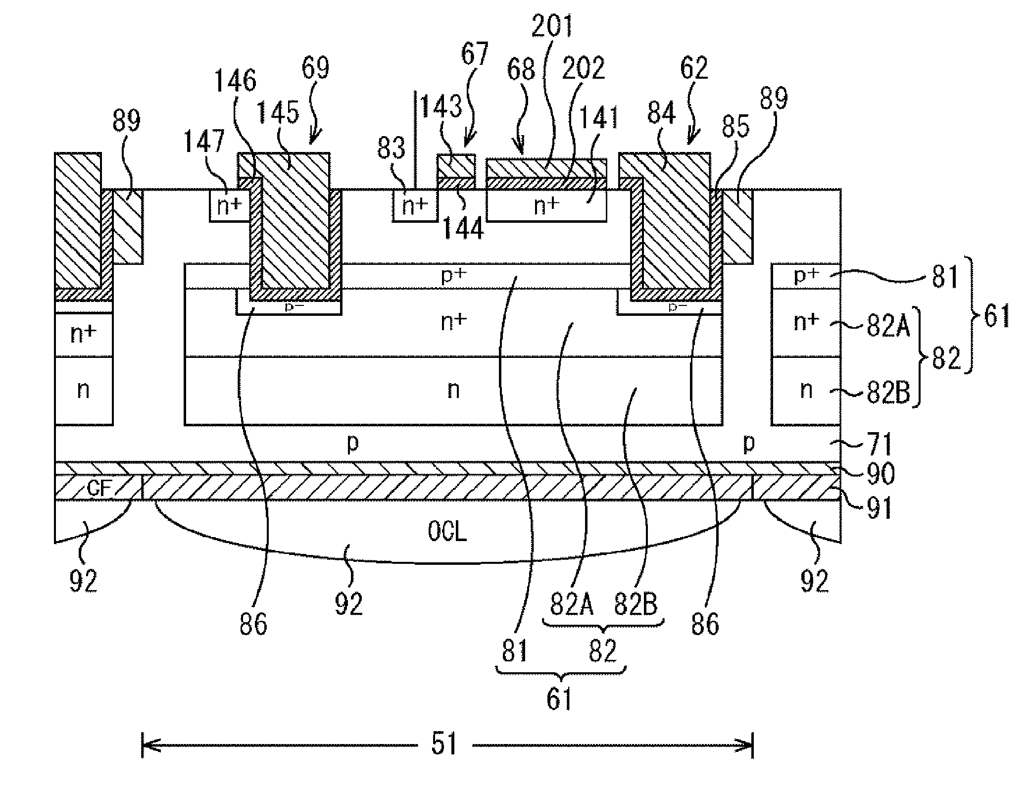
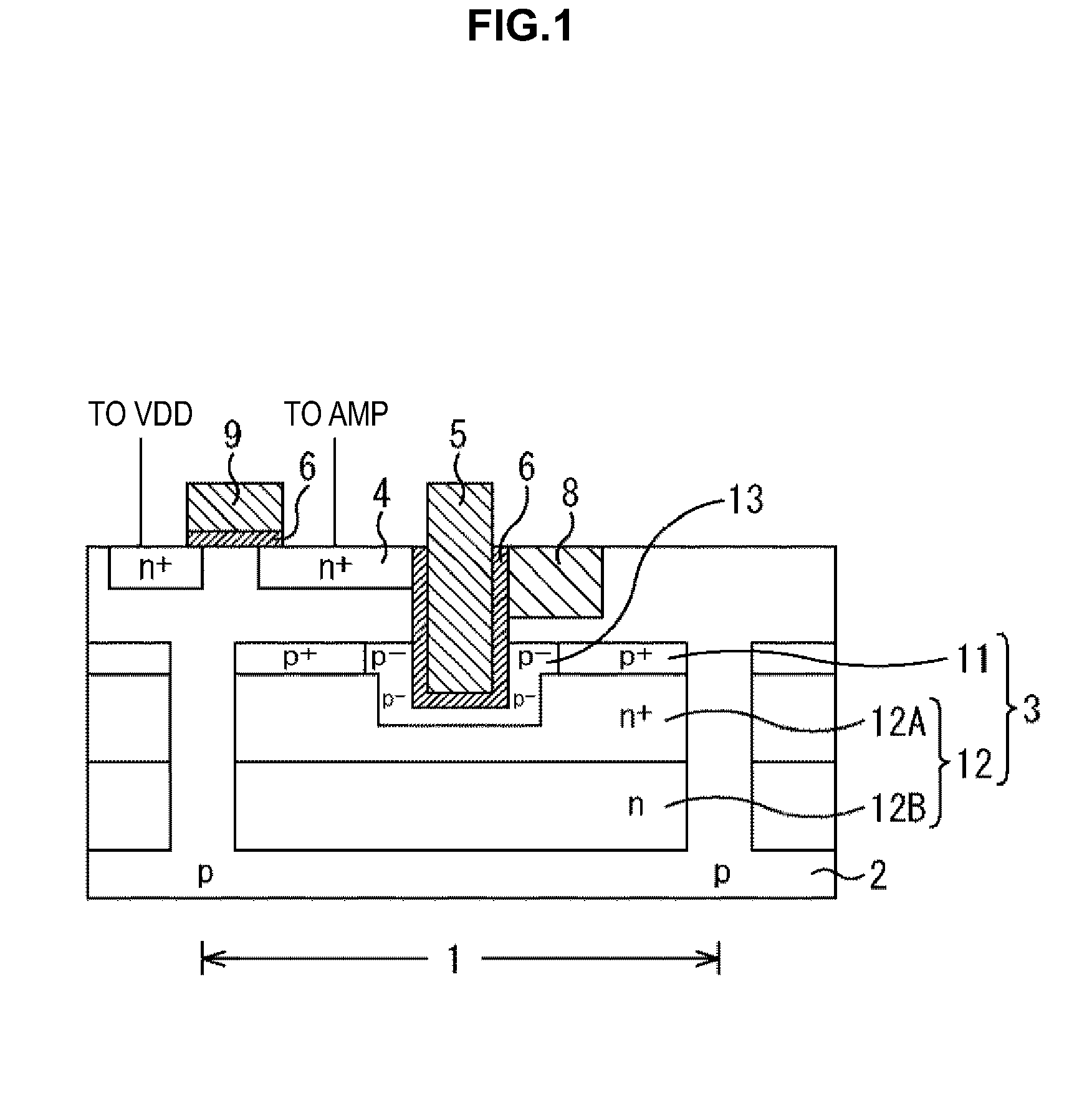
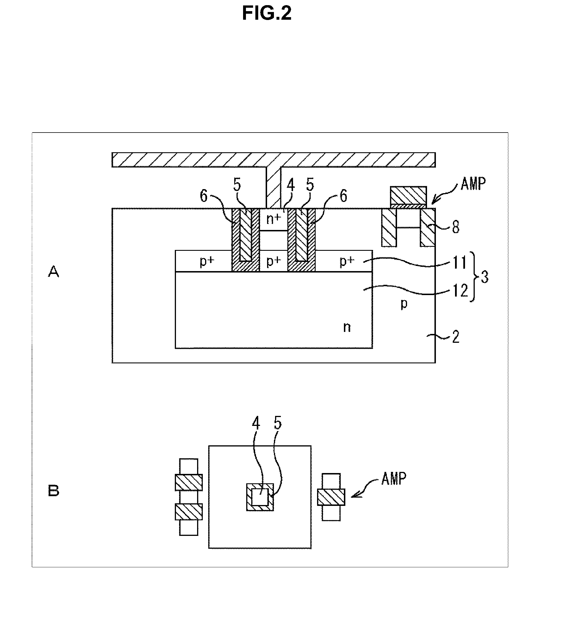
There is provided a solid state image sensor including a photoelectric conversion unit formed and embedded in a semiconductor substrate, an impurity region that retains an electric charge generated by the photoelectric conversion unit, and a transfer transistor that transfers the electric charge to the impurity region. A gate electrode of the transfer transistor is formed in a depth direction toward the photoelectric conversion unit in the semiconductor substrate, from a surface of the semiconductor substrate on which the impurity region is formed. A channel portion of the transfer transistor is surrounded by the gate electrode in two or more directions other than a direction of the impurity region, as seen from the depth direction.

Description

TECHNICAL FIELD[0001]The present technology relates to a solid state image sensor, its manufacturing method, and an electronic device, and particularly to a solid state image sensor, its manufacturing method, and an electronic device that configure a solid state image sensor tolerant to misalignment during manufacturing and having a high conversion efficiency of photoelectric conversion.BACKGROUND ART[0002]In a solid state image sensor (image sensor) using semiconductor (Si), a photo diode (PD) utilizing p-n junction of semiconductor is known as a photoelectric conversion element that converts a received light to an electrical signal. The element utilizing a photo diode is mounted on many electronic devices, such as a digital camera, a video camera, a monitoring camera, a copy machine, and a facsimile.[0003]In recent years, what is called CMOS solid state image sensor, which is manufactured by a complementary metal oxide semiconductor (CMOS) process including peripheral circuits, is...

Claims


Application Information

Patent Timeline
Patent Type & Authority Applications(United States)
IPC IPC(8): H01L27/146
CPCH01L27/14612H01L27/14689H01L27/14643H01L27/14614H01L27/14621H01L27/14627H01L27/14638H01L27/1464H01L27/14641H01L27/14647H01L27/14603H04N25/63H04N25/76
Inventor YAMAKAWA, SHINYA
Owner SONY SEMICON SOLUTIONS CORP
Why Eureka
Try Eureka