

Non-convalent patterned chemical features and use thereof in maldi-based quality control
a chemical feature and non-convalent technology, applied in the field of non-convalent patterned chemical features and use thereof in maldi-based quality control, can solve the problems of low density and relatively low fidelity of arrays, and achieve the effects of low cost, rapid screening and assessment, and fidelity and accuracy of target sequences
- Summary
- Abstract
- Description
- Claims
- Application Information
AI Technical Summary
Benefits of technology
Problems solved by technology
Method used
Image

Examples
example 1
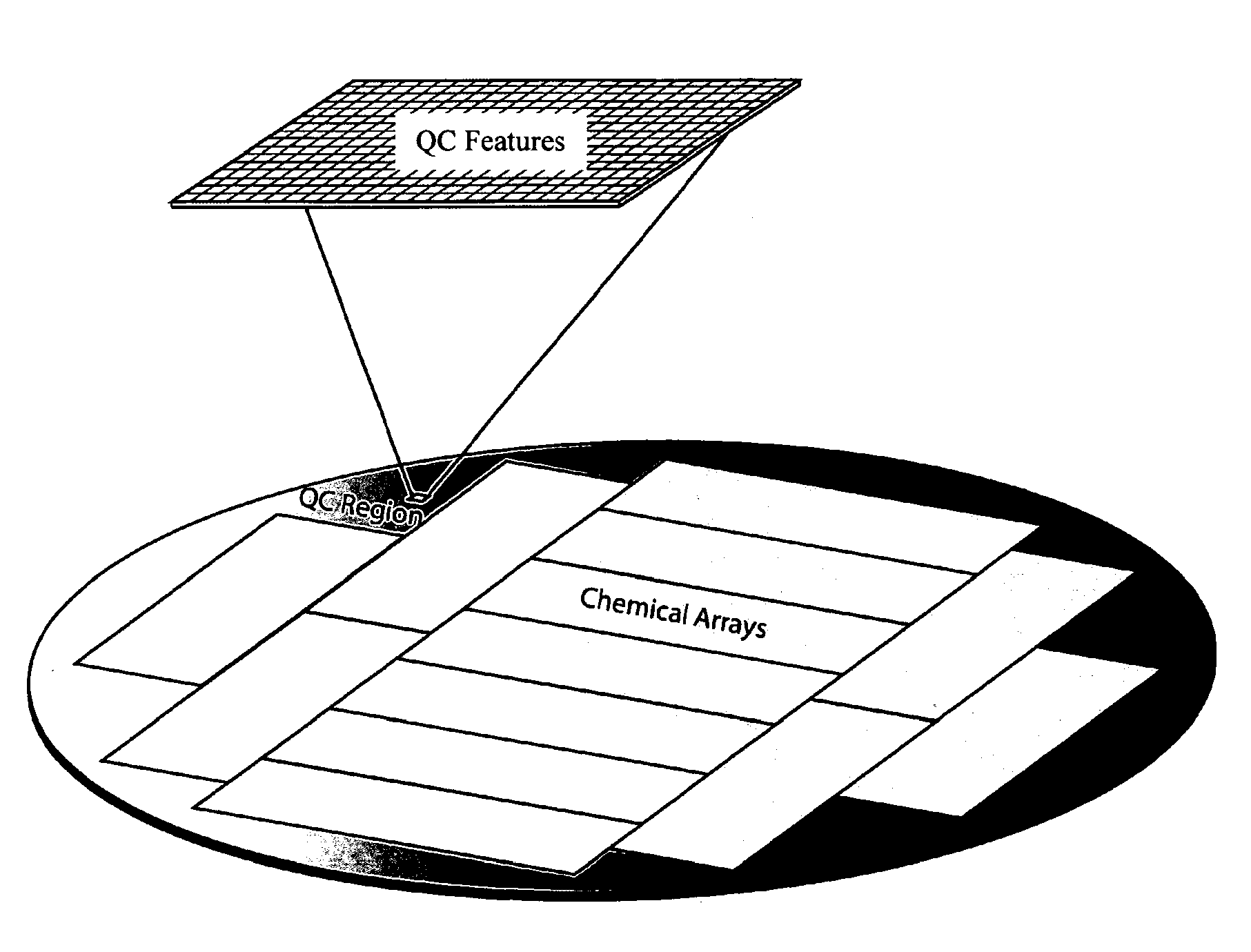
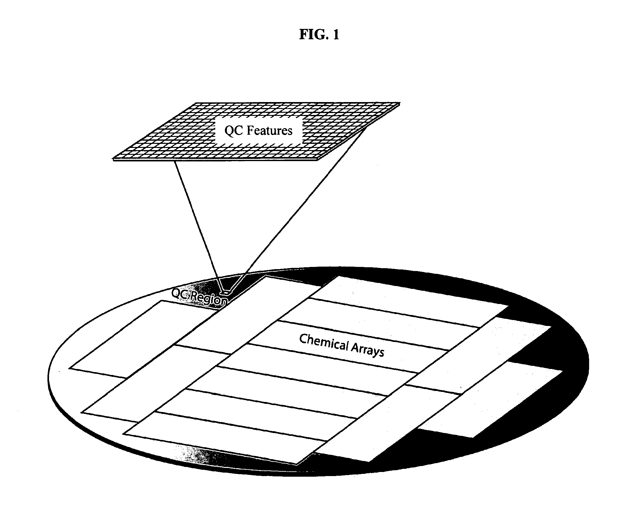
MALDI-TOF Image of a Quality Control (QC) Region of a Silicon Wafer
[0143]A silicon wafer with a thermal oxide coating and a monolayer of amino silane was subjected to bulk coupling via standard amino acid coupling chemistry to Boc glycine. Quality control (QC) features 200 microns in size were generated by photodeprotection of the Boc group (generation of acid by light in photoresist followed by removal of the photoresist). HMBA was coupled to these features. A peptide was then in situ synthesized on the HMBA. The peptide was eventually released from the surface using ammonia gas which resulted in peptides not diffusing. MALDI imaging of the surface was then performed and the results are given in. FIG. 12.
[0144]MALDI-TOF analysis was used to evaluate a defined area of an array that was designated for quality control analysis. FIG. 13 illustrates the MALDI spectra of a defined area of an array comprising specific QC features. Each feature in the array analyzed in FIG. 13 was 200 micr...
example 2
Correlating Surface MALDI Measurements with Sequence Dependent Monoclonal Antibody Binding
[0145]To correlate surface MALDI measurements with sequence dependent binding of monoclonal antibodies the average signals of three different monoclonal antibodies to features in a specific area of an array were measured. Binding of three select monoclonal antibodies to: a) their cognate sequences; and b) two other control sequences in a defined area of the array were measured.
[0146]FIG. 14 shows the average signals associated with binding of the three different monoclonal antibodies to an array of peptides. The three monoclonals tested in this experiment were P53 Ab1, P53 Ab8 and DM1A. In each case, the detected binding level of each antibody to their respective cognate sequences was greater than 50 times the detected level of noncognate binding (FIG. 15). The actual MALDI ion counts as a function of the mass-to-charge ratio for the three select features are shown in the top of FIG. 15. The bo...
example 3
Using MALDI Data to Monitor Photodeprotection and Coupling Steps in a Peptide Array Synthesis
[0148]FIG. 16 is a flowchart summarizing steps in a process that utilizes non-covalent patterned chemical features from a defined area of an array in a MALDI-based quality control analysis of the array.
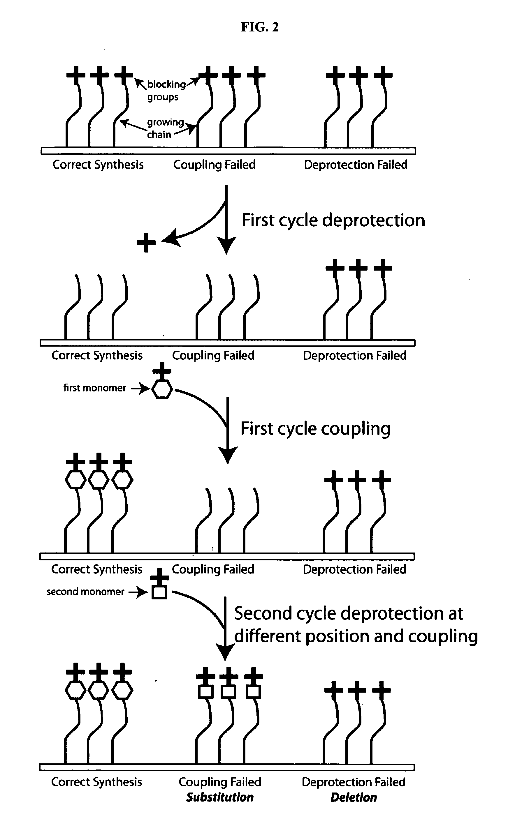
[0149]One of the first steps in the fabrication of an immunosignaturing array is to provide one or a plurality of feature(s) containing a linker peptide to the surface of the array 1601. The linker peptide can then exposed for further chemical coupling with, for example, a litography step 1602. To be available for further chemical coupling, the linker peptide needs to be exposed and deprotected in the lithography step 1603. Subsequently, additional amino acids can be coupled to the linker peptides in a step-wise fashion 1604-1605. This provides for a step-wise process whereby a desired amino acid can be incorporated into features that are present in an array. In some cases, peptides in feature...
PUM
 Abstract
Description
Claims
Application Information