Apparatus and Method for Preventing and Removing Carbon Deposits

a technology of apparatus and carbon, applied in mechanical apparatus, machines/engines, liquid cleaning, etc., can solve the problems of increasing the pressure drop of exhaust gases across the filter, the clogging of the filter pores, and the structure of the particulate filter, so as to prevent the increase of pressure drop across the filter, prevent efficiency losses, and increase the backpressure

Inactive Publication Date: 2016-02-18
TURGEON LUKE J +1
View PDF7 Cites 25 Cited by
  • Summary
  • Abstract
  • Description
  • Claims
  • Application Information

AI Technical Summary

Benefits of technology

[0025]Because the HHO generator may be mounted to the truck and may move with the truck, the HHO generator may provide HHO constantly whenever power is provided to the HHO generator, as when the diesel engine is operating. HHO may be injected continuously into the diesel engine exhaust gas upstream from the particulate filter to continuously clean solid carbon from the particulate filter to avoid accumulation of particulate matter in the filter. Continuously cleaning the solid carbon from the filter prevents an increa

Problems solved by technology

As soot accumulates in the particulate filter, the pores of the filter become clogged and the pressure drop of the exhaust gases across the filter increases.
If the regeneration step is not successful in adequately reducing the pressure drop across the particulate filter, the filter must be serviced or replaced.
If blowing out the soot and heating the filter are not successful in achieving an acceptable pressure drop, then the filter must be returned to the factory and replaced with a new filter.
Conventional regeneration, high-pressure air blowing and kiln-baking damages the structure of the particulate filter and shortens the life of its components.
The resulting thermal stresses on the ceramic core and on the seals of the particulate filter plus the physical violence of high-pressure air blowing shorten the structural life of the filter.
Even if cleaning of the filter is successful, substantial carbon remains in the filter after cleaning and the useful life of the clean

Method used


Image

  • Apparatus and Method for Preventing and Removing Carbon Deposits
  • Apparatus and Method for Preventing and Removing Carbon Deposits
  • Apparatus and Method for Preventing and Removing Carbon Deposits

Examples


Embodiment Construction

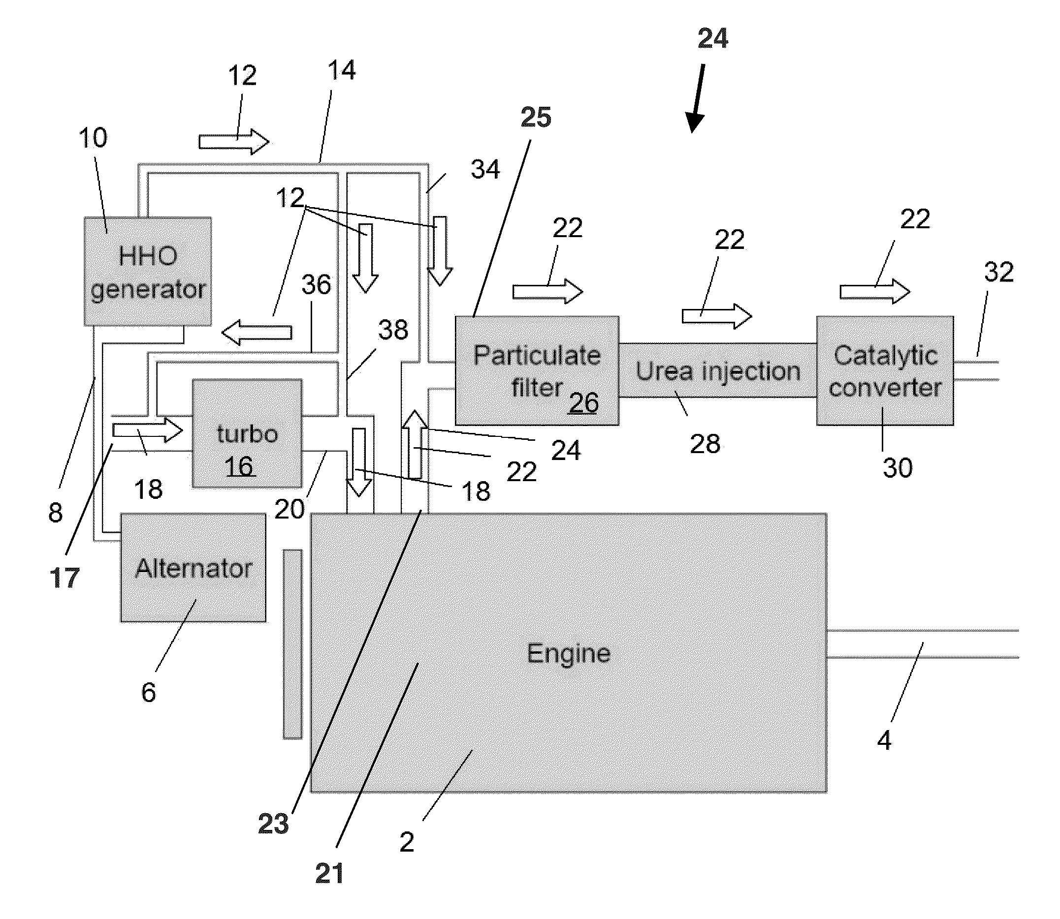
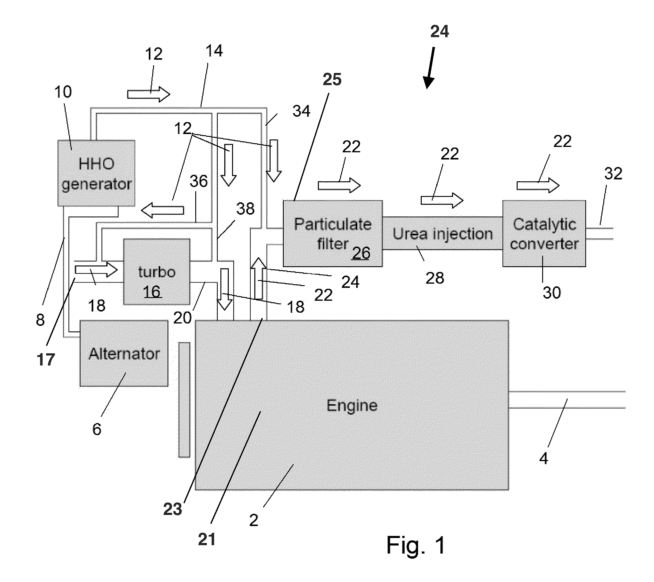
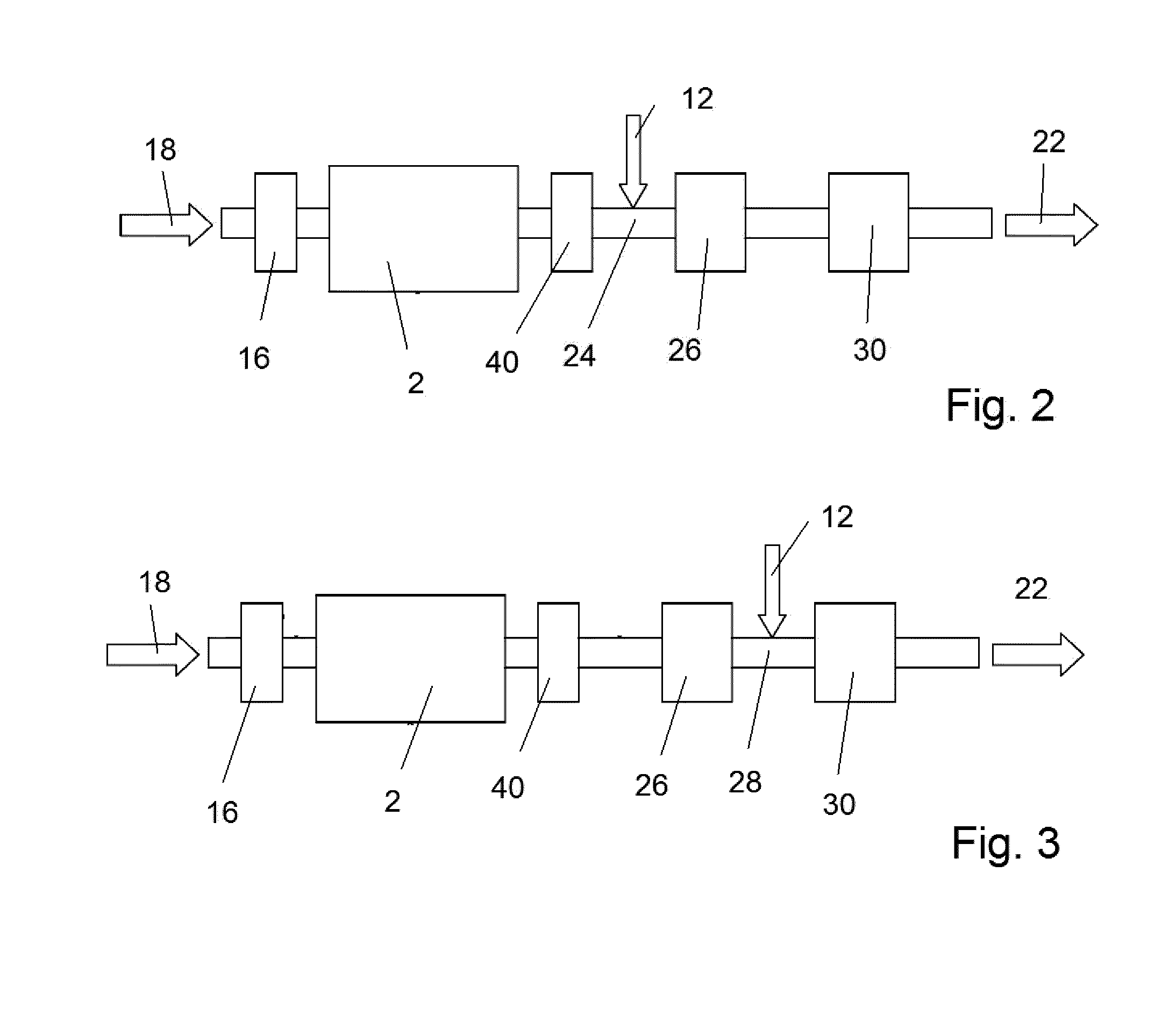
[0044]FIG. 1 illustrates power producing apparatus, such as a reciprocating internal combustion engine 2 that may be a diesel engine 2, with HHO generation and different locations for HHO injection. The diesel engine 2 rotates an output 4 which may provide motive power for a motor vehicle or for any other application. The engine 2 also drives an alternator 6 that generates electrical power that travels through wires8 to HHO generator 10. HHO generator 10 generates HHO 12 as described in U.S. Pat. No. 8,852,410, ‘Electrolytic hydrogen generator and method’ issued to Luke J. Turgeon, et al. on Oct. 7, 2014. Piping 14 conveys the HHO 12.

[0045]The example engine 2 is illustrated as being equipped with a turbocharger compressor 16, but the invention also applies to non-turbocharged engines 2 and to supercharged engines 2. Intake air 18 on a low-pressure side of the turbocharger compressor 16 at an intake 17 of the diesel engine 2 is compressed by turbocharger compressor 16 and conveyed f...


PUM


Abstract

Oxyhydrogen (HHO) generated by an HHO generator hydrogenates solid carbon to liquid and gaseous hydrocarbons in the exhaust system of an internal combustion engine, such as in the particulate filter of a diesel engine to clean the solid carbon from the particulate filter without conventional regeneration. Discharge of the HHO to the exhaust system also reacts with NOx in the exhaust gas to reduce the NOx. The HHO may be discharged to a plurality of locations to clean solid carbon and reduce NOx emissions from a diesel engine.

Description

I. RELATED APPLICATIONS[0001]This application is entitled to priority from U.S. Provisional Application 62 / 036,193 filed Aug. 12, 2014 by Luke J. Turgeon and entitled “apparatus and method for preventing and removing carbon deposits,” which is incorporated by reference as if set forth in full herein. The following document also is incorporated by reference as if set forth in full herein: U.S. Pat. No. 8,852,410, entitled ‘Electrolytic hydrogen generator and method,’ issued Oct. 7, 2014 to Luke J. Turgeon et al.II. BACKGROUND OF THE INVENTION[0002]A. Field of the Invention[0003]The Invention is an apparatus and method for removing carbon and preventing the buildup of carbon, such as carbon deposits on particulate filters of diesel engines. The Invention also applies to the removal of carbon and prevention of the build-up of carbon on the internal engine components of diesel and gasoline engines, including cylinders, pistons, piston rings, piston ring grooves and exhaust system.[0004]...

Claims


Application Information

Patent Timeline
IPC IPC(8): F01N3/029F01N3/023F01N3/035F02B77/04
CPCF01N3/0293F02B77/04F01N3/0237F01N3/035F01N3/2066F02B37/00F01N3/0253F01N2240/34F01N2610/04F01N13/009F02M25/12Y02A50/20Y02T10/12
Inventor TURGEON, LUKE J.VAN TIGGELEN, DOUGLAS
Owner TURGEON LUKE J
Why Eureka
Try Eureka