
Fuel cell system and method of controlling the fuel cell system

a fuel cell and system technology, applied in the direction of cell components, electrochemical generators, electrolytes, etc., can solve the problems of large number of components, inability to determine whether air has been mixed with water, and inability to supply stable and correct quantity of reforming water, etc., to achieve simple and economical structure, reduce the number of maintenance operations, and reduce the effect of ion exchange efficiency

Active Publication Date: 2016-03-03
HONDA MOTOR CO LTD
View PDF2 Cites 8 Cited by
  • Summary
  • Abstract
  • Description
  • Claims
  • Application Information

AI Technical Summary

Benefits of technology

The present patent aims to provide a fuel cell system and method of controlling it that can improve ion exchange efficiency, durability, reduce components, steps of maintenance, and prevent air from mixing into water. By measuring the electric conductivity of the water inside the ion exchanger, it is easy to determine if air has mixed in, which can cause a degradation in ion exchange efficiency and performance of other components. By detecting this, maintenance can be performed more efficiently, reducing the number of steps and identifying components that may need replacement at early stages.

Problems solved by technology

However, it is not possible to determine whether or not air has been mixed with the water to be supplied to the reforming unit 2a.
Therefore, it is not possible to supply a stable and correct quantity of the reforming water.
Further, since a partial oxidation reformer needs to be provided in addition to the steam reformer, the number of components is large, and the cost is high.
Further, in the conventional technique 2, it is not possible to determine whether or not air has been mixed with the condensed water supplied to the reformer 2b.
Therefore, it is not possible to supply a stable and correct quantity of the reforming water.
Further, since the water is discharged in the case where the electric conductivity of the condensed water is high, shortage of the reforming water may occur undesirably.
Thus, the number of components is large, and the cost is high.
Further, in the conventional technique 3, it is not possible to determine whether or not the air has been mixed into the condensed water to be supplied to the reformer.
Therefore, it is not possible to supply a stable and correct quantity of the reforming water.
Thus, the number of components is large, and the cost is high.

Method used


Image

  • Fuel cell system and method of controlling the fuel cell system
  • Fuel cell system and method of controlling the fuel cell system
  • Fuel cell system and method of controlling the fuel cell system

Examples


Embodiment Construction

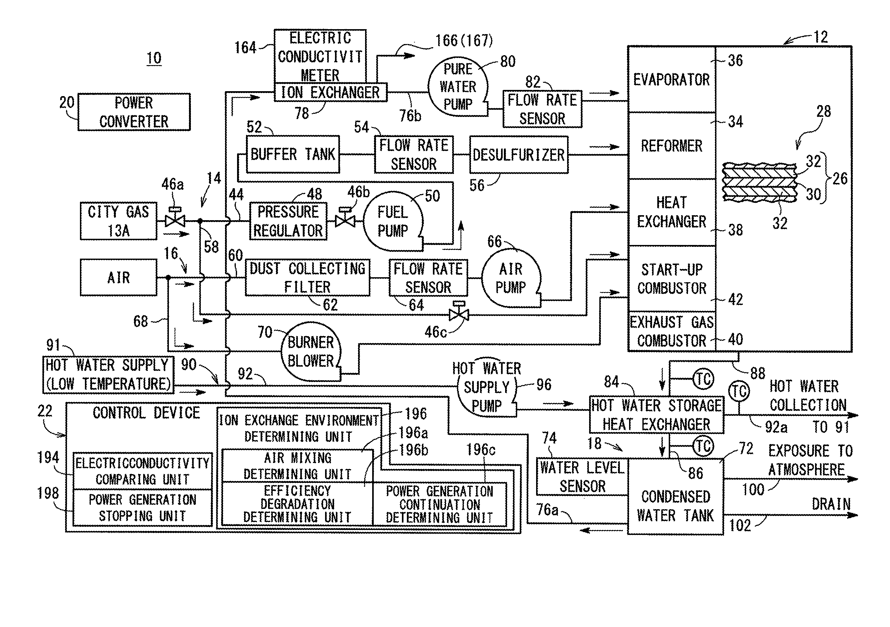
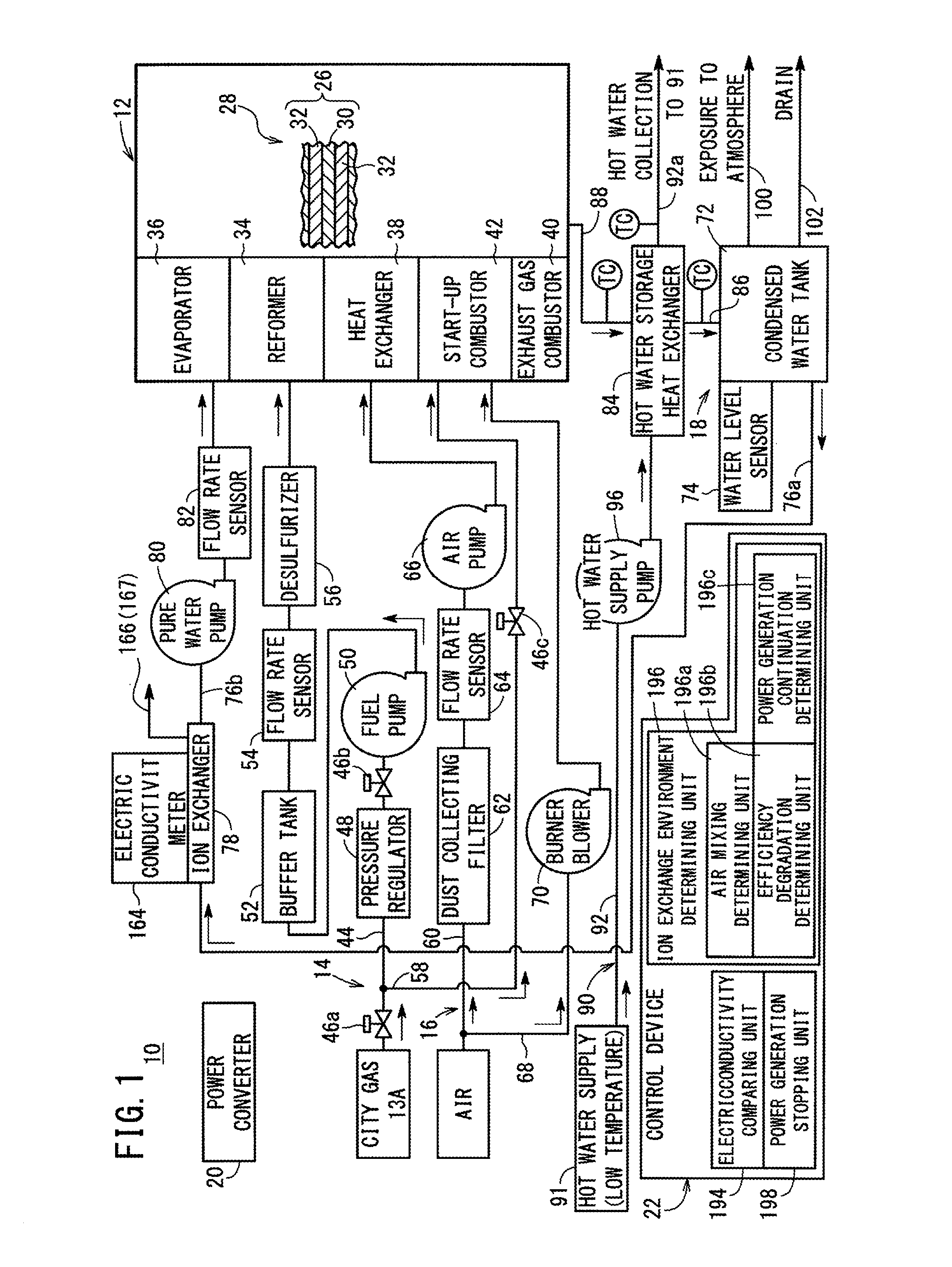
[0036]As shown in FIG. 1, a fuel cell system 10 according to a first embodiment of the present invention is used in a stationary application. However, the fuel cell system 10 can be used in various applications. For example, the fuel cell system 10 may be mounted in a vehicle.

[0037]The fuel cell system 10 includes a fuel cell module (SOFC module) 12 for generating electrical energy in power generation by electrochemical reactions of a fuel gas (e.g., mixed gas of a hydrogen gas, methane, and carbon monoxide) and an oxygen-containing gas (e.g., air), a fuel gas supply apparatus 14 for supplying a raw fuel (e.g., city gas) chiefly containing hydrocarbon as the fuel gas to the fuel cell module 12, an oxygen-containing gas supply apparatus 16 for supplying the oxygen-containing gas to the fuel cell module 12, a water supply apparatus 18 for supplying water to the fuel cell module 12, a power converter 20 for converting the direct current electrical energy generated in the fuel cell modu...


PUM

PropertyMeasurementUnit
electric conductivityaaaaaaaaaa
electric conductivity meteraaaaaaaaaa

Abstract

A control device of a fuel cell system includes an electric conductivity comparing unit for comparing the electric conductivity of the water inside the ion exchanger which is measured by the electric conductivity measuring unit with a predetermined electric conductivity range, and an ion exchange environment determining unit for arbitrarily determining whether or not air has been mixed into an ion exchanger and whether or not the ion exchange efficiency of the ion exchanger has been degraded, based on a comparison result by the electric conductivity comparing unit.

Description

TECHNICAL FIELD[0001]The present invention relates to a fuel cell system including a fuel cell stack formed by stacking a plurality of fuel cells for generating electrical energy by electrochemical reactions of a fuel gas and an oxygen-containing gas. Further, the present invention relates to a method of controlling the fuel cell system.BACKGROUND ART[0002]Typically, a solid oxide fuel cell (SOFC) employs a solid electrolyte of ion-conductive oxide such as stabilized zirconia. The solid electrolyte is interposed between an anode and a cathode to form an electrolyte electrode assembly (MEA). The electrolyte electrode assembly is interposed between separators (bipolar plates). In use, normally, predetermined numbers of the electrolyte electrode assemblies and the separators are stacked together to form a fuel cell stack.[0003]As the fuel gas supplied to the fuel cell, normally, a hydrogen gas produced from hydrocarbon raw material by a reformer is used. In general, in the reformer, a ...

Claims


Application Information

Patent Timeline
Patent Type & Authority Applications(United States)
IPC IPC(8): H01M8/04H01M8/06H01M8/12H01M8/24
CPCH01M8/04634H01M8/06H01M8/04223H01M8/0618H01M2250/20H01M8/1246H01M2008/1293H01M2300/0071H01M8/24B01J47/14Y02E60/525H01M8/04955H01M8/0687H01M8/04164H01M8/04395H01M8/04425H01M8/04492H01M8/04656H01M8/04686H01M8/04776Y02E60/50H01M8/04843Y02T90/40
Inventor YUZURIHA, AKIHITO
Owner HONDA MOTOR CO LTD
Learn More