Eureka AIR delivers breakthrough ideas for toughest innovation challenges, trusted by R&D personnel around the world.

Obtaining a Three-dimensional Image of a Medical Instrument with a Magnetic Resonance Tomography Device

Inactive Publication Date: 2016-03-17
SIEMENS AG
View PDF11 Cites 3 Cited by
  • Summary
  • Abstract
  • Description
  • Claims
  • Application Information

AI Technical Summary

Benefits of technology

The patent text describes a method using magnetic resonance tomography to create images of a person's body. These images can show the medical instrument used to treat the patient and the surrounding anatomical structures. The images can be combined and registered with each other, providing a more accurate view of the location of the medical instrument in relation to the patient's body. The text also mentions the use of markers to help identify and compensate for distortion in the images. The invention also includes a feature for the computing and control device to determine the position of the medical instrument and provide a planning device for the treatment.

Problems solved by technology

Aside from many advantages over other imaging methods, such as computed tomography, x-ray imaging, or ultrasound imaging, magnetic resonance tomography imaging has the disadvantage that image objects having a low water or fat content are principally only very poorly imaged in a magnetic resonance tomography image, and are therefore difficult to identify.
The disadvantage of using computed tomography is that the target organs may only be delimited inadequately, e.g., in small pelvis minors.
Magnetic resonance tomography would be suitable here, nevertheless with the disadvantage that applicators may now only be identified with difficulty.
This disadvantage is so significant that magnetic resonance tomography was previously barely used for this application.
Other failings of the magnetic resonance tomography, which play an important role in the dosimetry for EBRT methods, such as distortion, determination of attenuation values of the tissue, skin limits outside of the imaging region of the device, conversely hardly play any role in the brachytherapy because the target volume is close to the isocenter of the MR device.

Method used


Image

  • Obtaining a Three-dimensional Image of a Medical Instrument with a Magnetic Resonance Tomography Device
  • Obtaining a Three-dimensional Image of a Medical Instrument with a Magnetic Resonance Tomography Device
  • Obtaining a Three-dimensional Image of a Medical Instrument with a Magnetic Resonance Tomography Device

Examples


Embodiment Construction

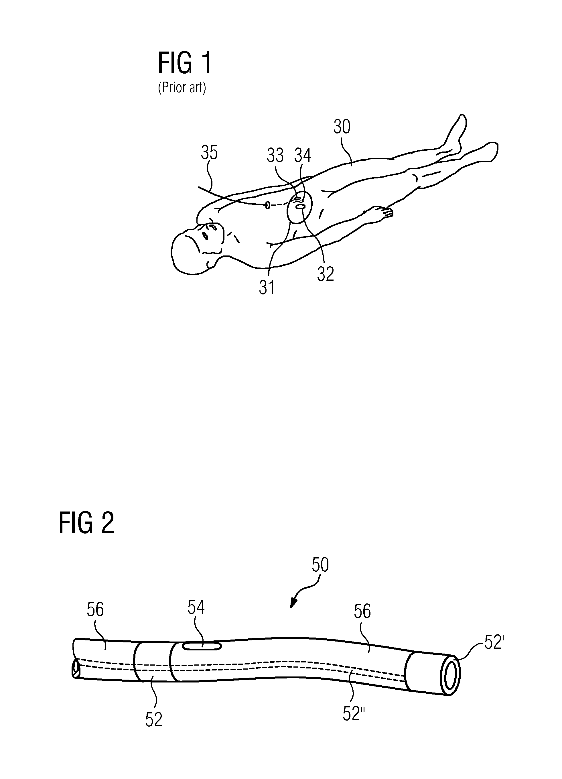
[0049]FIG. 1 depicts a representation to describe a brachytherapy according to the prior art. With an examination object 30, here a human patient, a brachytherapy is implemented to treat a target object 32, here a tumor. To this end, an applicator 35, here in the form of a catheter, is inserted into a target region 31. The target region 31 includes at least the target object 32, (e.g., the target region may be a volume within the examination object 30), within which at least the target object 32 is disposed. The applicator 35 allows a radiation device 33, here a so-called seed made of radionuclide, for instance cesium-137, cobalt-60, iridium-192, iodine-125, palladium-103 or ruthenium-106, or also a miniaturized low-energy x-ray emitter, to be brought into the immediate vicinity of the target object 32.

[0050]The radiation device 33 emits high-energy beams, indicated by lines 34 in FIG. 1, which penetrate the target object 32. A significant advantage of brachytherapy is that the radi...


PUM


Abstract

An apparatus is provided for obtaining a spatial instrument image of a medical instrument with a magnetic resonance tomography device, wherein the apparatus includes a medical instrument, a magnetic resonance tomography device, and a computing and control device. The medical instrument includes at least one marker material in at least one region, the marker material having a nuclear spin resonance outside of the proton resonance and wherein the computing and control device is configured to control the magnetic resonance tomography device such that a nuclear spin tomography imaging may be implemented by the magnetic resonance tomography device with the nuclear spin resonance of the at least one marker material in order to obtain a spatial instrument image, and wherein the computing and control device is configured to accept the instrument image. A corresponding medical instrument and a corresponding method are also provided.

Description

CROSS-REFERENCE TO RELATED APPLICATIONS[0001]This application claims the benefit of DE 10 2014 218 454.1, filed on Sep. 15, 2014, which is hereby incorporated by reference in its entirety.TECHNICAL FIELD[0002]The present embodiments relate to an apparatus for obtaining a spatial image of a medical instrument with a magnetic resonance tomography device. Furthermore, the present embodiments relate to a corresponding medical instrument and to a corresponding method for obtaining a spatial image of a medical instrument with a magnetic resonance tomography device.BACKGROUND[0003]Magnetic resonance tomography, nuclear spin tomography, or in short MRT, is a known imaging method, which is used in medical diagnostics for representing structures and functions of soft tissue and organs in an examination object, e.g., a human or animal patient. Aside from many advantages over other imaging methods, such as computed tomography, x-ray imaging, or ultrasound imaging, magnetic resonance tomography ...

Claims


Application Information

Patent Timeline
IPC IPC(8): A61B5/06A61B5/00A61B5/055A61N5/10G06T7/00G06T11/00G06T11/60
CPCA61B5/062A61N5/1001A61B5/055G06T2207/10088G06T11/003G06T7/0042G06T11/60A61B5/7282A61B5/064A61N5/1049A61N2005/1055A61B90/39G01R33/286A61B34/20
Inventor GRODZKI, DAVIDHAUSOTTE, ANNEMARIEHEISMANN, BJORNHENGERER, ARNEKELLER-REICHENBECHER, MARK-ALEKSISCHMIDT, SEBASTIAN
Owner SIEMENS AG
Why Eureka
Eureka Blog
Learn More