

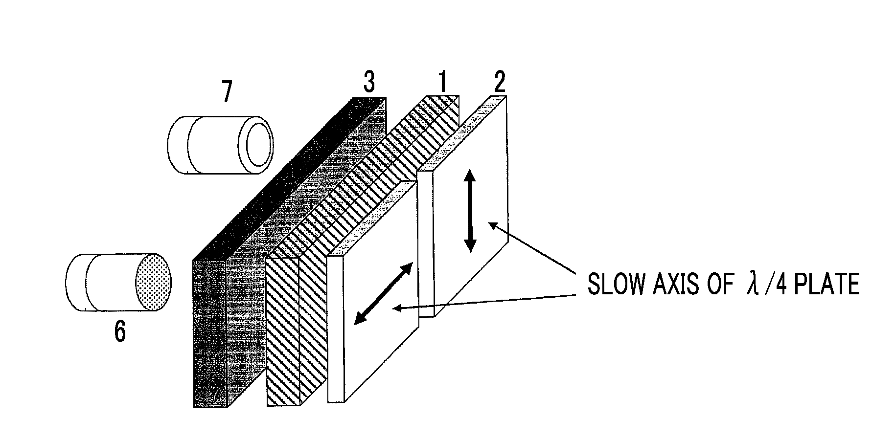
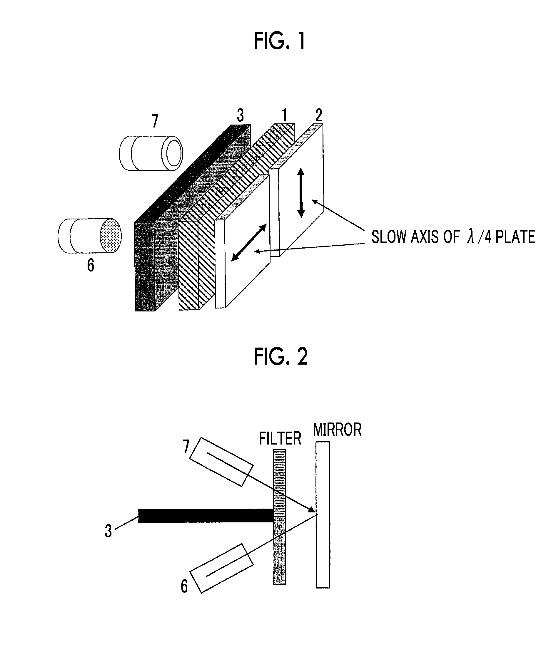
Polarization filter and sensor system
a technology of polarization filter and sensor system, applied in the field of polarization filter, can solve the problems of reduced light intensity and light degree, and achieve the effect of improving the sensitivity of the detection system, preventing the reduction of sensitivity, and being highly sensitiv
- Summary
- Abstract
- Description
- Claims
- Application Information
AI Technical Summary
Benefits of technology
Problems solved by technology
Method used
Image

Examples
example 1
[0177]The rubbing-processed surface of PET manufactured by FUJIFILM Corporation that had undergone rubbing processing was coated with a coating solution A-2 shown in Table 1 at room temperature by using a wire bar such that the thickness of the film obtained after drying became 5 μm. The coating layer was dried for 30 seconds at room temperature and then heated for 2 minutes in an atmosphere with a temperature of 85° C. Thereafter, by using a D bulb (lamp of 90 mW / cm) manufactured by Fusion UV Systems Inc., the coating layer was irradiated with UV rays for 6 to 12 seconds at 30° C. at 60% of output, thereby obtaining a liquid crystal layer. The liquid crystal layer was coated with a coating solution A-3 shown in Table 1 at room temperature such that the thickness of the film obtained after drying became 5 μm. Subsequently, drying, heating, and UV irradiation were performed on the coating solution in the same manner as described above so as to form a second liquid crystal layer, ther...
example 2
[0186]The rubbing-processed surface of PET manufactured by FUJIFILM Corporation that had undergone rubbing processing was coated with a coating solution A-1 shown in Table 1 at room temperature by using a wire bar, such that the thickness of the film obtained after drying became 5 μm. The coating layer was dried for 30 seconds at room temperature and then heated for 2 minutes in an atmosphere with a temperature of 85° C. Thereafter, by using a D bulb (lamp of 90 mW / cm) manufactured by Fusion UV Systems Inc., the coating layer was irradiated with UV rays for 6 to 12 seconds at 30° C. at 60% of output, thereby obtaining a liquid crystal layer. The liquid crystal layer was coated with the coating solution A-2 shown in Table 1 at room temperature such that the thickness of the film obtained after drying became 5 μm. Subsequently, drying, heating, and UV irradiation were performed on the coating solution in the same manner as described above, thereby obtaining a second liquid crystal lay...
example 3
[0188]The rubbing-processed surface of PET manufactured by FUJIFILM Corporation that had undergone rubbing processing was coated with the coating solution A-1 shown in Table 1 at room temperature by using a wire bar, such that the thickness of the film obtained after drying became 5 μm. The coating layer was dried for 30 seconds at room temperature and then heated for 2 minutes in an atmosphere with a temperature of 85° C. Thereafter, by using a D bulb (lamp of 90 mW / cm) manufactured by Fusion UV Systems Inc., the coating layer was irradiated with UV rays for 6 to 12 seconds at 30° C. at 60% of output, thereby obtaining a liquid crystal layer. The liquid crystal layer was coated with the coating solution A-2 shown in Table 1 at room temperature such that the thickness of the film obtained after drying became 5 μm. Subsequently, drying, heating, and UV irradiation were performed on the coating solution in the same manner as described above, thereby obtaining a second liquid crystal l...
PUM
 Abstract
Description
Claims
Application Information