
Vibration wave drive device, stator for a vibration wave motor, vibration wave motor, driving control system, optical apparatus, and manufacturing method of a vibration wave driving device

a technology of vibration wave motor and drive device, which is applied in the direction of piezoelectric/electrostrictive/magnetostrictive devices, piezoelectric/electrostriction/magnetostriction machines, etc., can solve the problem that the piezoelectric body between the ground electrode and the ground electrode cannot effectively apply a voltage, and the non-driving region of the piezoelectric element cannot actively expand or contract. achieve the effect of reducing the cos

Active Publication Date: 2016-04-28
CANON KK
View PDF6 Cites 13 Cited by
  • Summary
  • Abstract
  • Description
  • Claims
  • Application Information

AI Technical Summary

Benefits of technology

The patent text discusses the problem of reducing performance and quality, as well as increasing cost, in vibration actuators caused by the use of power feeding members that prevent the piezoelectric element from expanding and contacting, resulting in inhibited performance. The present invention provides a solution to this problem by providing a vibration wave drive device, stator, vibration wave motor, driving control system, optical apparatus, and manufacturing method that achieve higher performance, quality, and lower cost of the actuator without inhibiting active expansion and contraction of the piezoelectric element.

Problems solved by technology

Therefore, the piezoelectric element in the non-driving region cannot actively expand or contract.
The electrode for ground and the ground electrode are electrically connected to each other through intermediation of the elastic member, and hence the piezoelectric body between the electrode for ground and the ground electrode is not effectively applied with a voltage.

Method used


Image

  • Vibration wave drive device, stator for a vibration wave motor, vibration wave motor, driving control system, optical apparatus, and manufacturing method of a vibration wave driving device
  • Vibration wave drive device, stator for a vibration wave motor, vibration wave motor, driving control system, optical apparatus, and manufacturing method of a vibration wave driving device
  • Vibration wave drive device, stator for a vibration wave motor, vibration wave motor, driving control system, optical apparatus, and manufacturing method of a vibration wave driving device

Examples


example 1

[0169]As the piezoelectric material 1, commercially available lead zirconate titanate (PZT) was used to produce the annular piezoelectric material 1 illustrated in FIG. 10A. The Curie temperature of lead zirconate titanate (PZT) is 310° C.

[0170]Next, through screen printing of silver paste, the common electrode 2 was formed on one surface of the annular piezoelectric material 1 as illustrated in FIG. 3C, while the polarizing electrodes 33, the driving phase power supply electrodes 34, the ground electrodes 5 and 6, and the detection phase electrode 7 were formed on the other surface of the annular piezoelectric material 1 as illustrated in FIG. 10B. At this time, the inter-electrode distance of adjacent electrodes illustrated in FIG. 10B was set to 0.5 mm.

[0171]Next, between the common electrode 2 and the polarizing electrodes 33, the ground electrodes 5 and 6, and the detection phase electrode 7, polarization processing was performed in air with use of a DC power supply so that the...

example 2

[0176]As the piezoelectric material 1, similarly to Example 1, lead zirconate titanate (PZT) was used to produce the annular piezoelectric material 1.

[0177]Next, through screen printing of silver paste, the common electrode 2 was formed on one surface of the annular piezoelectric material 1, while the polarizing electrodes 33, the ground electrodes 5 and 6, and the detection phase electrode 7 were formed on the other surface of the annular piezoelectric material 1. The driving phase power supply electrodes 34 provided in Example 1 were not provided.

[0178]Next, similarly to Example 1, between the common electrode 2 and the polarizing electrodes 33, the ground electrodes 5 and 6, and the detection phase electrode 7, polarization processing was performed in air with use of a DC power supply so that the polarity of expansion and contraction of the piezoelectric element became as illustrated in FIG. 4B.

[0179]Next, in order to connect the polarizing electrodes 33, the connection electrode...

example 3

[0183]As the piezoelectric material 1, the following materials were used to produce the annular piezoelectric material 1.

[0184]First, as a raw material, barium titanate having an average particle diameter of 100 nm (manufactured by SAKAI CHEMICAL INDUSTRY CO., LTD.: BT-01 (product name)), calcium titanate having an average particle diameter of 300 nm (manufactured by SAKAI CHEMICAL INDUSTRY CO., LTD.: CT-03 (product name)), and calcium zirconate having an average particle diameter of 300 nm (manufactured by SAKAI CHEMICAL INDUSTRY CO., LTD.: CZ-03 (product name)) were weighed at a molar ratio of 81.3:12.7:6.0.

[0185]Next, those weighed powders were dry-mixed for 24 hours with use of a ball mill. In order to granulate the obtained mixed powder, 0.26 parts by weight of manganese(II) acetate on a manganese metal basis with respect to the mixed powder and 3 parts by weight of a PVA binder with respect to the mixed powder were caused to adhere to surfaces of the mixed powder with use of a...


PUM


Abstract

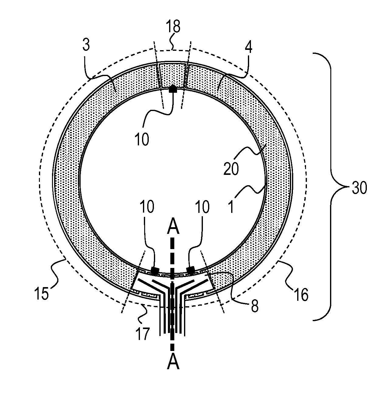
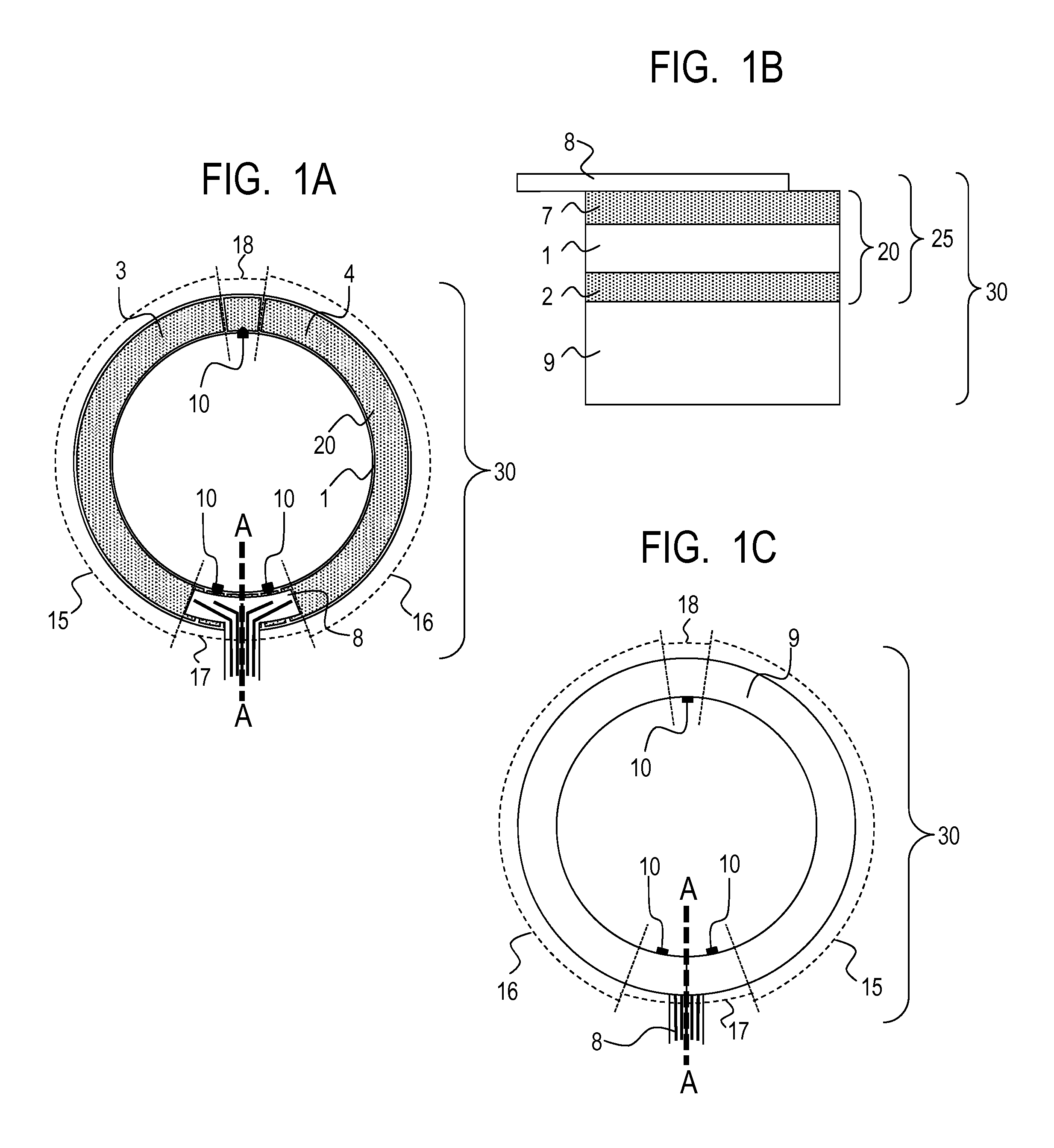
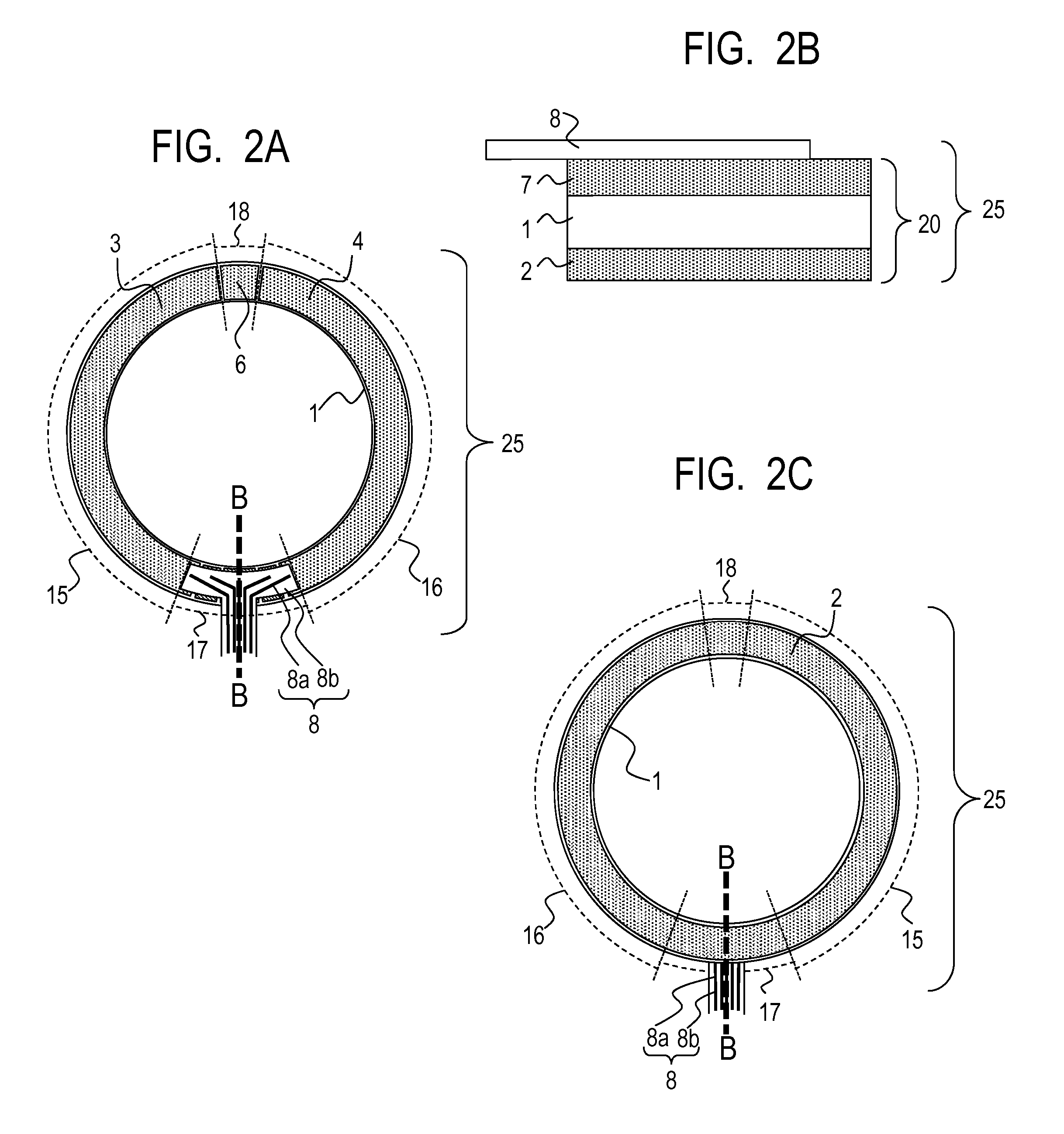
A vibration wave drive device (25) includes an annular piezoelectric element (20) including a piezoelectric material (1) and multiple electrodes provided sandwiching the piezoelectric material (1), the annular piezoelectric element being configured to vibrate by a traveling wave of a wavelength λ; and a power feeding member (8) including at least electric wire (8a) for supplying electric power to the element (20), the feeding member (8) being provided to a first surface of the element (20). The element (20) includes at least two driving regions (15, 16), and a non-driving region (17) arranged between two of the at least two driving regions and has an average annular length of nλ / 4, n being an odd number. At least one electrode provided on the first surface is arranged across the region (15, 16) and the region (17), and is electrically connected to the feeding member (8) only in the region (17).

Description

TECHNICAL FIELD[0001]The present invention relates to a vibration wave drive device, a stator for a vibration wave motor, a vibration wave motor, a driving control system, an optical apparatus, and a manufacturing method of a vibration wave driving device. In particular, the present invention relates to a power feeding member for supplying electric power to an electrode of, for example, an annular vibration wave motor in which an electric-mechanical energy converting element is used to excite vibrations in a vibrating member and the resulting vibrational energy is used to generate a drive force.BACKGROUND ART[0002]A vibration (vibration wave) actuator includes a vibrator that excites drive vibrations to an annular, oblong, or rod-shaped elastic member when an electrical signal, such as an alternating voltage, is applied to an electric-mechanical energy converting element, such as a piezoelectric element. As an example of the vibration actuator, there is proposed a vibration wave mot...

Claims


Application Information

Patent Timeline
IPC IPC(8): H02N2/16H01L41/29H01L41/257H02N2/14H01L41/047
CPCH02N2/163H02N2/14H01L41/29H01L41/257H01L41/0475H02N2/0085H10N30/045H10N30/06H10N30/875
Inventor IFUKU, TOSHIHIROFURUTA, TATSUOTAKEDA, KENICHIKOYAMA, SHINYATANAKA, HIDENORIFUJITA, SATOSHI
Owner CANON KK
Learn More